-28-
Electrical Adjustments
[1080i-A/D INPUT ADJUSTMENT]
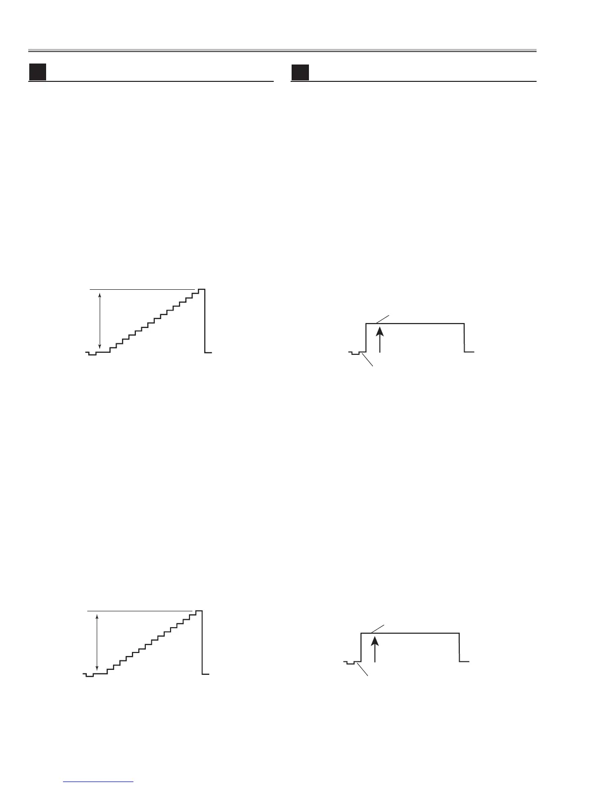
1. Receive the 16-step gray scale component signal
[1080i] with Video [Y/Pb,Pr/Cb,Cr] mode.
2. Enter the service mode.
3. Connect an oscilloscope to test point “TP13G”(+)
and chassis ground (-).
4. Select group no. “3”, Item no. “1” and adjust the ampli-
tude “a” to be 1.35 ±0.1V by changing the Data value.
5. Connect an oscilloscope to test point “TP13B”(+)
and chassis ground (-).
6. Select Item no. “3” and adjust the amplitude “a” to be
1.35 ±0.1V by changing the Data value.
7. Connect an oscilloscope to test point “TP13R”(+)
and chassis ground (-).
8. Select Item no. “4” and adjust the amplitude “a” to be
1.35 ±0.1V by changing the Data value.
[480p-A/D INPUT ADJUSTMENT]
1. Receive the 16-step gray scale component signal
[480p] with Video [Y/Pb,Pr/Cb,Cr] mode.
2. Enter the service mode.
3. Connect an oscilloscope to test point “TP13G”(+)
and chassis ground (-).
4. Select group no. “3”, Item no. “1” and adjust the ampli-
tude “a” to be 1.35 ±0.1V by changing the Data value.
5. Connect an oscilloscope to test point “TP13B”(+)
and chassis ground (-).
6. Select Item no. “3” and adjust the amplitude “a” to be
1.35 ±0.1V by changing the Data value.
7. Connect an oscilloscope to test point “TP13R”(+)
and chassis ground (-).
8. Select Item no. “4” and adjust the amplitude “a” to be
1.35 ±0.1V by changing the Data value.
A/D Input adjustment [Component]
12
[1080i-PEDESTAL ADJUSTMENT]
1. Receive the 100%whole-Black component signal
[1080i] with Video [Y/Pb,Pr/Cb,Cr] mode.
2. Enter the service mode.
2. Enter the service mode.
3. Connect an oscilloscope to test point “TP531”(+) and
chassis ground (-).
4. Select group no. “5”, Item no. “11” and adjust the black
level to be maximum amplitude by changing the Data
value.
5. Connect an oscilloscope to test point “TP501”(+) and
chassis ground (-).
6. Select Item no. “12” and adjust the black level to be
maximum amplitude by changing the Data value.
7. Connect an oscilloscope to test point “TP561”(+) and
chassis ground (-).
8. Select Item no. “13” and adjust the black level to be
maximum amplitude by changing the Data value.
[480p-PEDESTAL ADJUSTMENT]
1. Receive the 100%whole-Black component signal
[480p] with Video [Y/Pb,Pr/Cb,Cr] mode.
2. Enter the service mode.
3. Connect an oscilloscope to test point “TP531”(+) and
chassis ground (-).
4. Select group no. “5”, Item no. “11” and adjust the black
level to be maximum amplitude by changing the Data
value.
5. Connect an oscilloscope to test point “TP501”(+) and
chassis ground (-).
6. Select Item no. “12” and adjust the black level to be
maximum amplitude by changing the Data value.
7. Connect an oscilloscope to test point “TP561”(+) and
chassis ground (-).
8. Select Item no. “13” and adjust the black level to be
maximum amplitude by changing the Data value.
Note: These adjustments should be done after A/D
Input adjustment [Component].

 Loading...