-29-
1. Receive the 1dot Black/White computer signal with
Computer 1 [Analog RGB] mode.
2. Enter the service mode.
3. Project only green light component to the screen.
4. Select group no. “5”, Item no. “9”and change Data
value to obtain the minimum flicker on the screen.
5. Project only blue light component to the screen.
6. Select Item no. “10 and change Data value to obtain
the minimum flicker on the screen.
7. Project only red light component to the screen.
8. Select Item no. “8” and change Data value to obtain
the minimum flicker on the screen.
Common Center adjustment
16
[PC WHITE BALANCE ADJUSTMENT]
1. Receive the 100%-whole white computer signal with
Computer 1 [Analog RGB] mode.
2. Enter the service mode.
3. Select group no. “4”, Item no. “7” (Red) or “8”(Blue),
and change Data values respectively to make a prop-
er white balance.
[AV WHITE BALANCE ADJUSTMENT]
4. Receive the 100%-whole white video signal with
Video mode.
5. Enter the service mode.
6. Select group no. “4”, Item no. “7” (Red) or “8”(Blue),
and change Data values respectively to make a prop-
er white balance.
White Balance adjustment
17
If you find the color shading at the some part of the
screen, it needs to take the color shading adjustment.
This adjustment should be performed by a computer
and it also requires a special software “Color Shading
Correction”. The software will be supplied separately
and can be ordered as follows;
COLOR SHADING CORRECTION SOFTWARE
Ser
vice Parts No. 645 051 2308
NOTE ON WHITE UNIFORMITY
ADJUSTMENT
1. Receive the 100%whole-white composite video signal
with Video mode.
2. Enter the service mode.
3. Measure luminance on the screen with the luminance
meter. It is A for the reading of luminance meter.
4. Change the signal source to the 50%whole-white
composite video signal with Video [Video] mode.
5. Select group no. “4”, Item no. “6” and change the Data
value to make the reading of luminance meter to be A
x 22%
.
Luminance adjustment [Video]
15
Electrical Adjustments
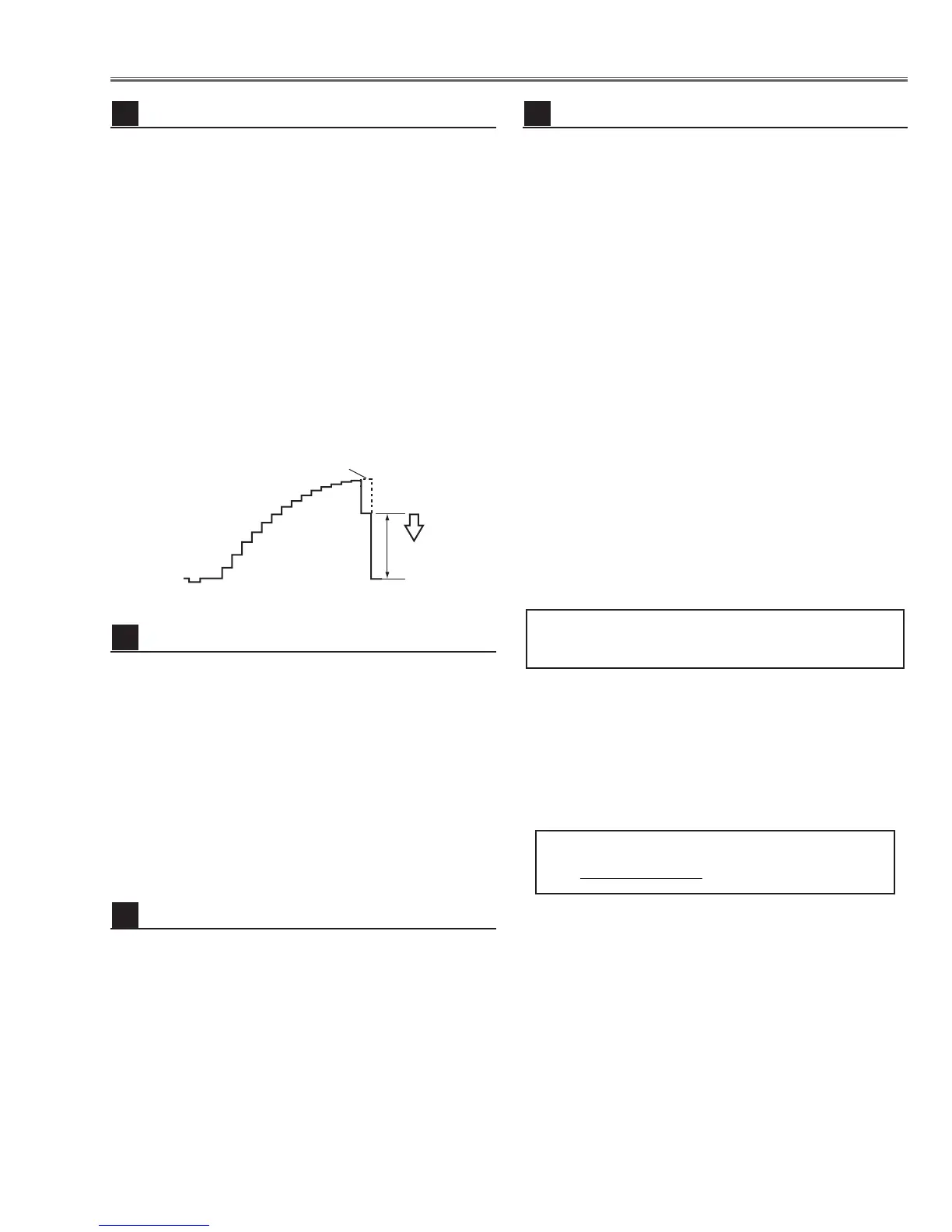
1. Receive the 16-step gray scale component signal
[1080i] with Video [Y/Pb,Pr/Cb,Cr] mode.
2. Enter the service mode.
3. Connect an oscilloscope to test point “TP531”(+)
and chassis ground (-).
4. Select group no. “4”, Item no. “3” and adjust the white
level to be minimum amplitude by changing the Data
value.
5. Connect an oscilloscope to test point “TP501”(+)
and chassis ground (-).
6. Select Item no. “4” and adjust the white level to be
minimum amplitude by changing the Data value.
7. Connect an oscilloscope to test point “TP561”(+)
and chassis ground (-).
8. Select Item no. “5” and adjust the white level to be
minimum amplitude by changing the Data value.

 Loading...