-26-
Electrical Adjustments
1. Receive the 16-step grey scale 480i-component signal
with Computer1 [Component] mode.
2. Enter the service mode.
3. Connect an oscilloscope to test point “TPG1” (+) and
chassis ground (-).
4. Select group no. “0”, item no. “0” and change data val-
ue to adjust the pedestal level and black level to be the
same level.
5. Connect an oscilloscope to test point “TPR1” (+) and
chassis ground (-).
6. Select item no. “1” and change data value to adjust the
pedestal level and black level to be the same level.
7. Connect an oscilloscope to test point “TPB1” (+) and
chassis ground (-).
8. Select item no. “2” and change data value to adjust the
pedestal level and black level to be the same level.
Pedestal Lebel
Black Lebel
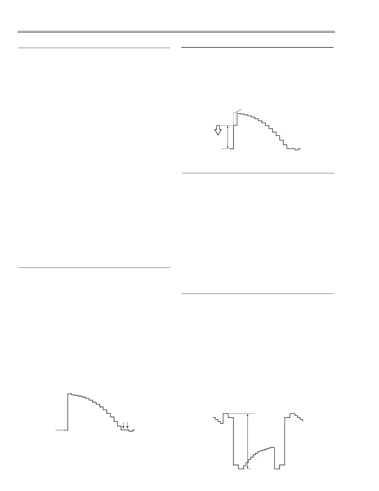
c Pedestal adjustment [480i]
1. Receive the 16-step grey scale 480i-component signal
with Computer1 [Component] mode.
2. Enter the service mode.
3. Connect an oscilloscope to test point “TPG1” (+) and
chassis ground (-).
4. Select group no. “0”, item no. “3” and adjust the ampli-
tude “a” to be minimum by changing the Data value.
v Gain adjustment [480i]
1. Receive the 16-step grey scale computer signal with
Computer1 [RGB] mode.
2. Enter the service mode.
3. Connect an oscilloscope to test point “TPG1” (+) and
chassis ground (-).
4. Select group no. “100”, item no. “124” and change data
value to adjust amplitude “a” to be 10.0 ±0.1V.
5. Connect an oscilloscope to test point “TPR1” (+) and
chassis ground (-).
6. Select item no. “125” and change data value to adjust
amplitude “a” to be 10.0 ±0.1V.
7. Connect an oscilloscope to test point “TPB1” (+) and
chassis ground (-).
8. Select item no. “126” and change data value to adjust
amplitude “a” to be 10.0 ±0.1V.
(a)
black level
black level
n Black Reference adjustment
1. Enter the service mode.
2. Receive the 16-step grey scale computer signal with
Computer1 [RGB] mode.
3. To start the auto-calibration for PC adjustment, select
group no. “260”, item no. “0” and then change data
value from “0” to “1”. After the auto-calbration com-
pleted, "OK" will appear on the screen.
4. Receive the 16-step grey scale composite video sig-
nal with Video mode.
5. To start the auto-calibration for Video adjustment,
select group no. “260”, item no. “0” and then change
data value from “0” to “1”. After the auto-calbration
completed, "OK" will appear on the screen.
b Auto Calibration adjustment
1. Eenter the service mode.
2. Connect a digital voltmeter to test point “TPFANA” (+)
and chassis ground (-). Select group no. “250”, item
no. “95” and change data value to adjust voltage to be
13.5 ±0.1V.
3. Connect a digital voltmeter to test point “TPFANB” (+)
and chassis ground (-). Select item no. “97” and change
data value to adjust voltage to be 13.5 ±0.1V.
4. Connect a digital voltmeter to test point “TPFANA”
(+) and chassis ground (-). Select item no. “94” and
change data value to adjust voltage to be 5.0 ±0.1V.
5. Connect a digital voltmeter to test point “TPFANB”
(+) and chassis ground (-). Select item no. “96” and
change data value to adjust voltage to be 5.0 ±0.1V.
x Fan Control adjustment
 Loading...