Do you have a question about the Sanyo PLV-Z800 and is the answer not in the manual?
| Resolution | 1920 x 1080 |
|---|---|
| Lamp Life | 2000 hours (Normal Mode), 3000 hours (Eco Mode) |
| Lens Shift | Vertical: ±100%, Horizontal: ±50% |
| Projection Size | 40 - 300 inches |
| Brightness | 1200 ANSI lumens |
| Contrast Ratio | 15000:1 |
| Zoom Ratio | 2x |
| Inputs | HDMI, Component, Composite, S-Video |
| Display Technology | 3LCD |
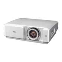
Details the type of projector covered in the service manual.
Essential safety precautions to be observed during servicing.
Notice regarding product safety and component replacement.
Specific warnings for service personnel regarding operation and hazards.
Detailed technical specifications of the projector.
Steps for cleaning or replacing the projector's air filters.
Procedure to reset the lamp replacement counter.
Method to check the total lamp usage time.
Guidance on necessary adjustments after replacing components.
Procedures for performing optical adjustments on the projector.
How to enter and navigate the service adjustment menu.
Procedures for fine-tuning projector circuits at the factory.
Diagram of the video signal processing and LCD panel driving circuits.
Block diagram showing system control circuits and their interconnections.
Diagram illustrating the motor driving circuits for iris and door mechanisms.
Schematic of the fan control circuit, including sensors and fan operation.
Diagrams of the power supply and secondary power protection circuits.
A flowchart to diagnose projector conditions based on indicator states.
Table correlating projector status indicators with specific conditions.
Troubleshooting steps for projector no-power issues based on LED indicators.
Diagnostic steps for troubleshooting no picture issues across various input sources.
Diagrams showing the physical location of electrical components.
Diagram illustrating the location of cabinet-related parts.
Diagrams showing the location of optical components.