16
The Sapling Company, Inc.
1633 Republic Road
Huntingdon Valley, PA 19006
USA
P. (+1) 215.322.6063
F. (+1) 215.322.8498
www.sapling-inc.com
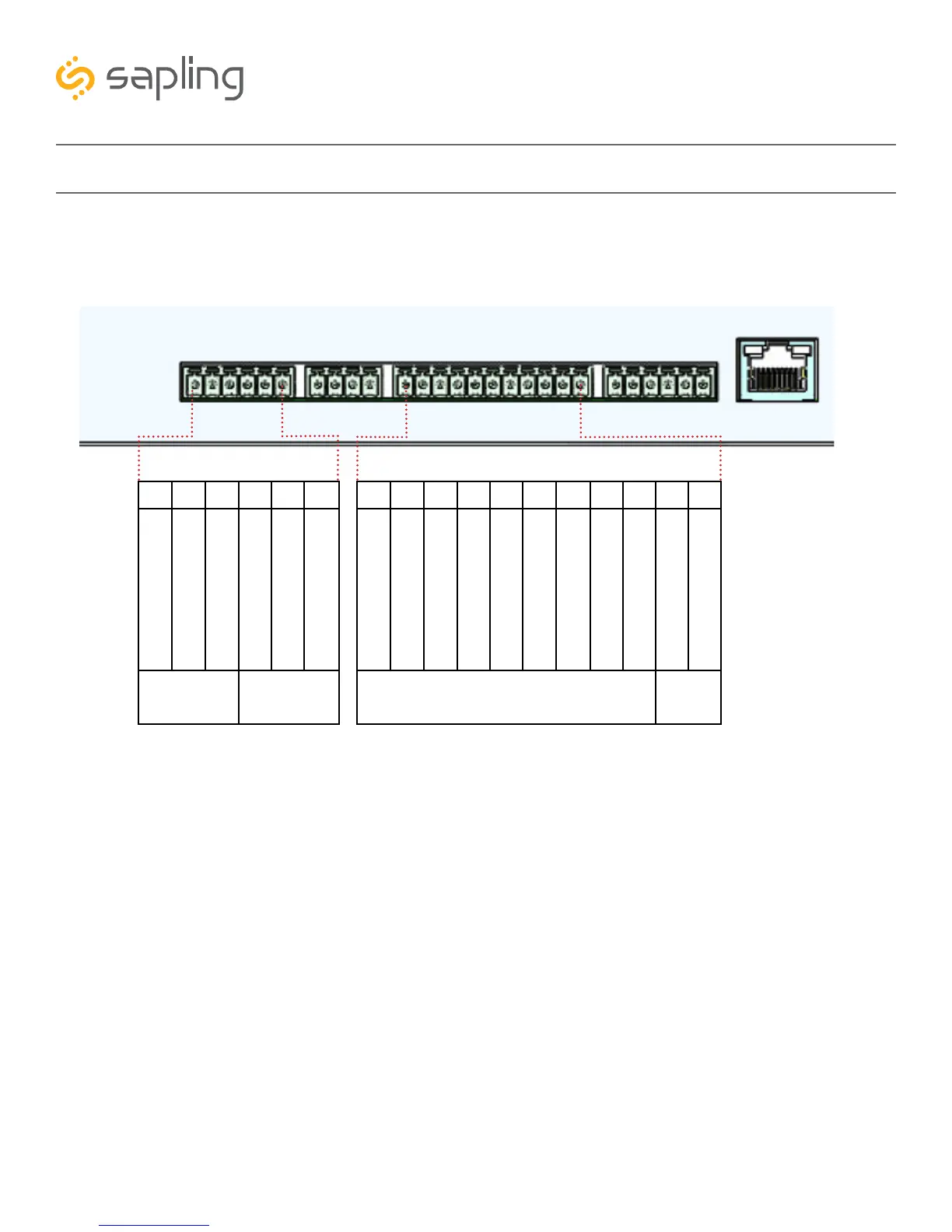
If your master clock is set to receive data through wires from another device as its primary time input, the
wires must be attached to the proper ports on the master clock. The diagram below shows the locations
and the functions of each port.
Inputs and Outputs - Sync-Wire
Consult the wiring diagrams on the following pages for information on how to install wiring specific to
your synchronization method. Relevant port numbers will be listed with each diagram.
IMPORTANT: Your master clock will only accept input from another device if you command it to do so
through the web interface or front panel pushbuttons. For information on how to do this, please see the
section labeled Web Interface - Synchronization
Outputs
27 26 25 24 23 22
Clock 1
Sync Relay
Clock 2
Sync Relay
Normally Open
Normally Open
Normally Closed
Normally Closed
Normally Common
Relay Common
17 16 15 14 13 12 11 10 9 8 7
Sync Inputs
V Out
40ma
AC/DC Common
Dukane Reset
Alarm Common
24VAC Sync
Alarm 12VDC/24VAC
5VDC Dry Contact
+5VDC
Dukane Min. Pulse
Common
120VAC Sync
1Rauland Digital
 Loading...