中文
EN DE RU KO PT JA ES
03015/03017
36
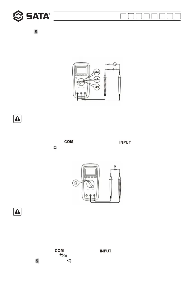
Measuring resistance:
1) Connect the black test probe to the " " jack and the red test probe to the " " jack.
2) Set the function switch to position.
3) Connect the test probes to both ends of the resistor to be measured.
4) Take readings on the screen.
Note:
1) When the resistance is greater than 1MQ, the reading may take several seconds to stabilize. This is normal for high
resistance measurements.
2) When the input terminal is open circuited, "OL" will appear on the screen to indicate overrange.
3) Before measuring the resistance of the circuit, make sure to disconnect the power to the circuit to be measured and
fully discharge all capacitors.
Note:
If the range of the current to be measured is unknown, firstly set the function switch to the highest level of range and then
adjust it to the lower level step by step until a satisfactory range is obtained.
Continuity test:
1) Connect the black probe to " " jack and the red probe to " " jack.
2) Set the function switch to the " " position.
3) Press the " " button until the " " symbol appears on the screen.
4) Connect the test probes to both ends of the circuit to be measured.
3) Press the " " button to select the AC current or DC current measurement function and the corresponding symbol will appear
on the screen.
4) Disconnect the power to the circuit to be measured, connect the test probes in series to it, and then switch on its power.
5) Read the reading indicated on the screen. During DC current measurement, the polarity of connecting end of the red probe will be
indicated.