2 TD-1 SATEL
3. Electronics board description
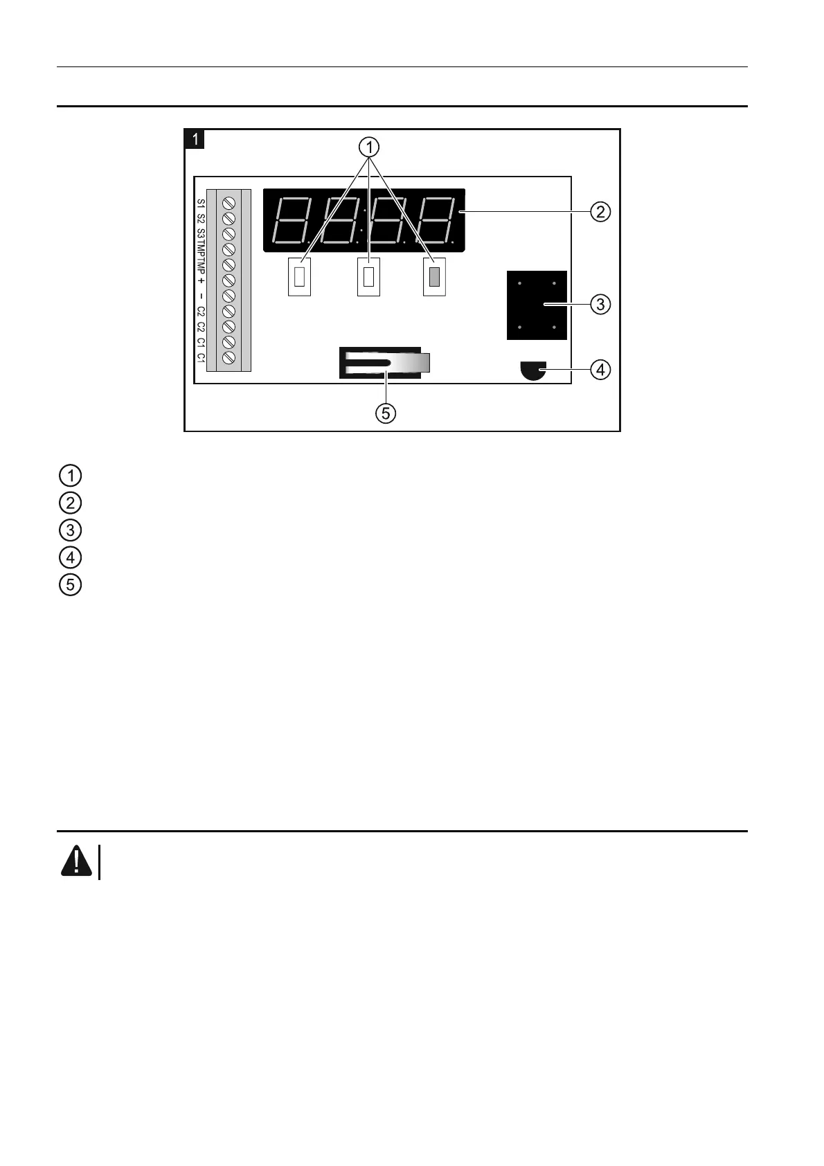
Fig. 1. Detector PCB.
buttons for navigating through menus and programming.
LED display.
sounder.
temperature sensor.
tamper contact.
Description of terminals:
S1 ÷ S3 - input for connecting an external sensor or bistable switch.
TMP - tamper contact.
+ - power input (12 V DC ±15%).
- - common ground.
C2 - relay output 2.
C1 - relay output 1.
4. Installation
All electrical connections may only be made with disconnected power supply.
The tools to be useful during installation include:
flat blade screwdriver, 1 mm,
tweezers,
precision pliers.
The TD-1 detector should be installed in closed spaces with normal air humidity. The
waterproof probe can be installed outdoors.
1. Open the enclosure and remove the electronics board.
2. Make the openings for screws and wires in the enclosure base.
3. Pass the wires through the prepared openings.