SATEL TD-1 3
4. Fix the enclosure base to the wall.
S3
input must be configured during programming (see description of the function F9 p. 6).
5. Fasten the electronics board.
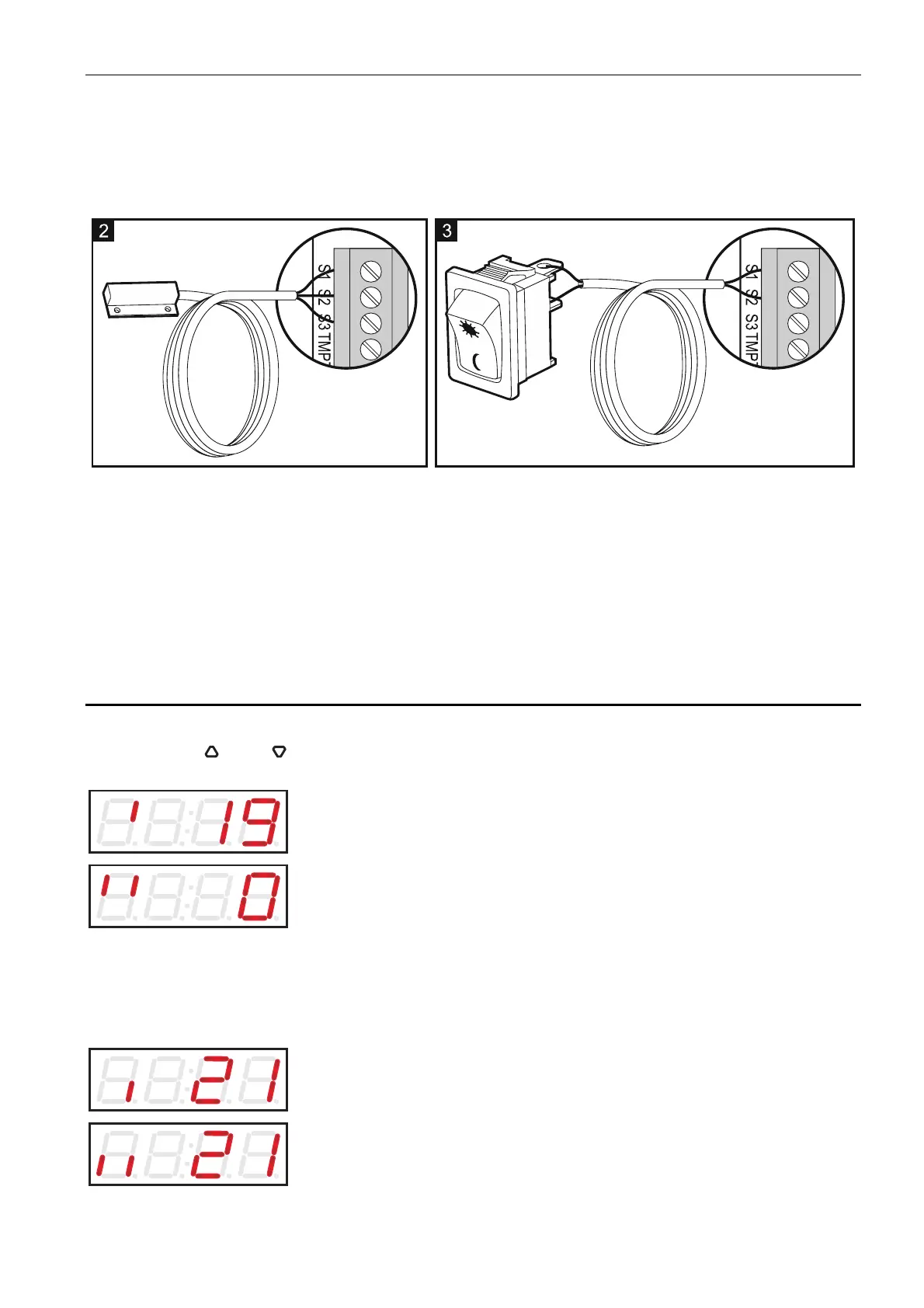
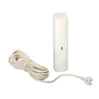
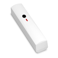
6. Connect an external probe (Fig. 2: S1 – red wire and the screen (covered with black heat
shrink tube), S2 – green wire, S3 – white wire) or a bistable switch (Fig. 3). The S1-
7. Connect the power wires to the terminals “+” and “-”.
8. Connect the devices to be controlled by the detector to the relay terminals. The outputs
must be configured during programming (see descriptions of the functions F10 p. 6, F11
p. 7).
11. Program the detector as needed.
p. 6, F13 p. 7 and F14
9. Close the enclosure.
10. Turn on the detector power.
5. Operation
The display always shows the current temperature. If the external probe is connected, you
can use the and buttons to select the sensor the temperature from which will be
presented.
temperature from the internal sensor.
If both sensors measure the temperature in the same ro
temperature from the external sensor.
Note: om, the difference between
re from internal sensor
and information about the currently enabled set of critical parameters.
the temperature readouts from the sensors can be 1 °C.
If a bistable switch is connected, the display will present the temperatu
the first set.
the second set.