x10
11
RT-TGP/RT-BT OWNER’S MANUAL
ASSEMBLY & INSTALLATION
PAGES:
11-44
Assembling the 27” x 16” Cast Iron Router Table
Requires:
27” x 16” Cast Iron Router Table with Hardware
Phillips Head Screwdriver
1
2
3
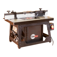
Remove the protective covering from
the table. (1.1) Wipe off the oil with a
soft, clean cloth.
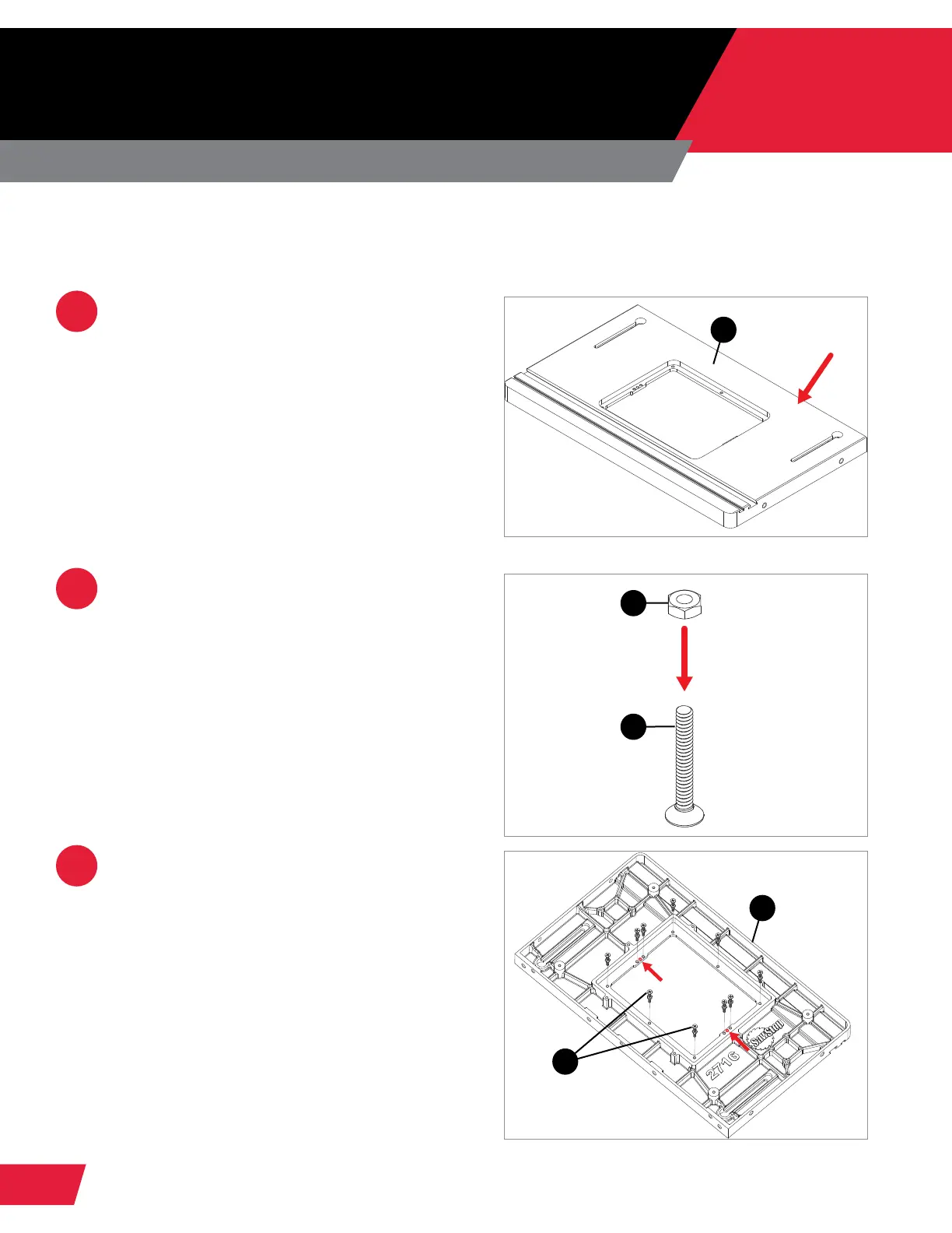
Thread ten hex nuts (1.2) halfway onto
ten at head Phillips screws (1.3).
Place the router table (1.1) upside down
on a at surface and thread the at head
Phillips screws (1.3) into the threaded
holes around the insert opening in the
table until they extend about ¼” below
the table’s top surface. These screws
will support and level the router lift
relative to the table top. The 2 holes in
the center of the opening (shown in red)
do not receive leveling screws; they will
be used later to attach the router lift to
the router table.
1.1
1.1
1.2
1.3
1.3