26
Note the following QVS color codes as mapped to the RS-232C (EIA-561) Jack:
QVS ADAPTOR
WIRE COLOR
FUNCTION
IMPLEMENTED IN
THE ETHERMETER?
BLUE RING INDICATOR NO
ORANGE DCD (OR CTS) YES
BLACK DTR YES (TIED TO V+)
RED SIG GND YES
GREEN
RxD (DATA RECEIVED
BY ETHERMETER)
YES
YELLOW
TxD (DATA TRANSMITTED
BY ETHERMETER)
YES
BROWN CTS NO (BUT SEE DCD (ORANGE) ABOVE)
WHITE RTS YES
RS-485 Serial Port
The RS-485 serial port is implemented within three (3) Phoenix Contact screw terminals. The
pinout is as described in Section 4.
In order to activate the RS-485 serial port, the 2
nd
dip switch should be placed in the “down”
position. Note that either the RS-232C or RS-485 serial port can be activated, but not both
simultaneously.
When the EtherMeter is staged at the endpoint of the transmission line, a 120 Ohm termination
resistor should be used. For convenience, a 120 Ohm, ½ Watt resistor is included as a feature
within the device. To activate the termination resistor, the 3
rd
dip switch should be placed in the
“up” position. In all other cases, this resistor should be disabled with the dip switch in the “down”
position.
A DC common reference terminal is included with the RS-485 port (terminal 22). This fused
terminal is connected to the device’s DC common through a 120 Ohm, ½ Watt current-limiting
resistor. It is important to note that the RS-485 serial port is not optically-isolated, and therefore
port isolation and/or TVSS may be required.
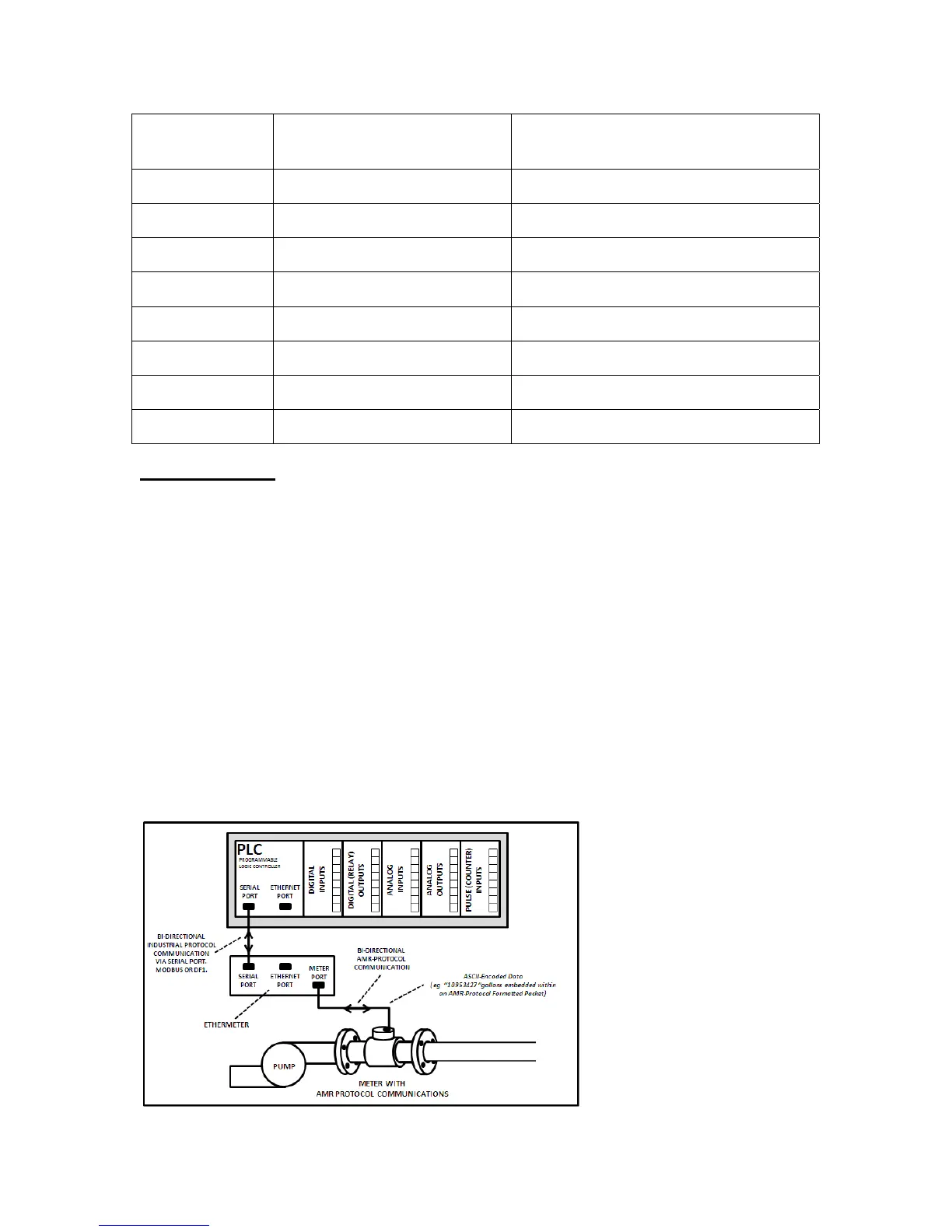
An example of an EtherMeter™ connected to the serial port of a PLC.