29
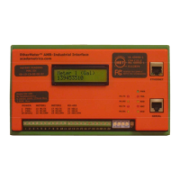
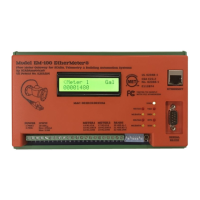
12 AUXILIARY I/O CHANNELS
As an added benefit, the EtherMeter is equipped with 4 auxiliary inputs and outputs. These
additional I/O make the device suitable for deployment as a standalone RTU at low-complexity
locations, such as master meter vaults or even simple pumping stations.
Auxiliary I/O
Type
Notes
Digital
Input(s)
(0,1,2, or 3)
Dry Contact Only.
Closed = ON (1)
Open = OFF (0)
Non-Isolated, Fused.
Digital
Output(s)
(0,1,2 or 3)
0-5V TTL
Requires an external NRTL-Listed or Recognized Solid-State Relay.
eg. Power-IO P/N IO-ODC-60 for DC loads, or Power-IO P/N IO-OAC-280 for
AC loads.
Digital Output #1 can be used for radio power-saver output.
Non-Isolated, Fused.
Analog
Input 1
4-20mA (default) or 0-5VDC.
0-5VDC is activated by removing JP1 (inside case).
4-20mA loop resistance = 240 Ohms.
AIN1- is connected to DC Common (GND).
Caution: AIN1+ should NEVER be connected to a voltage greater than 5VDC
above the DC common.
(See Recommended Wiring Diagram later in this section.)
Non-Isolated, Fused.
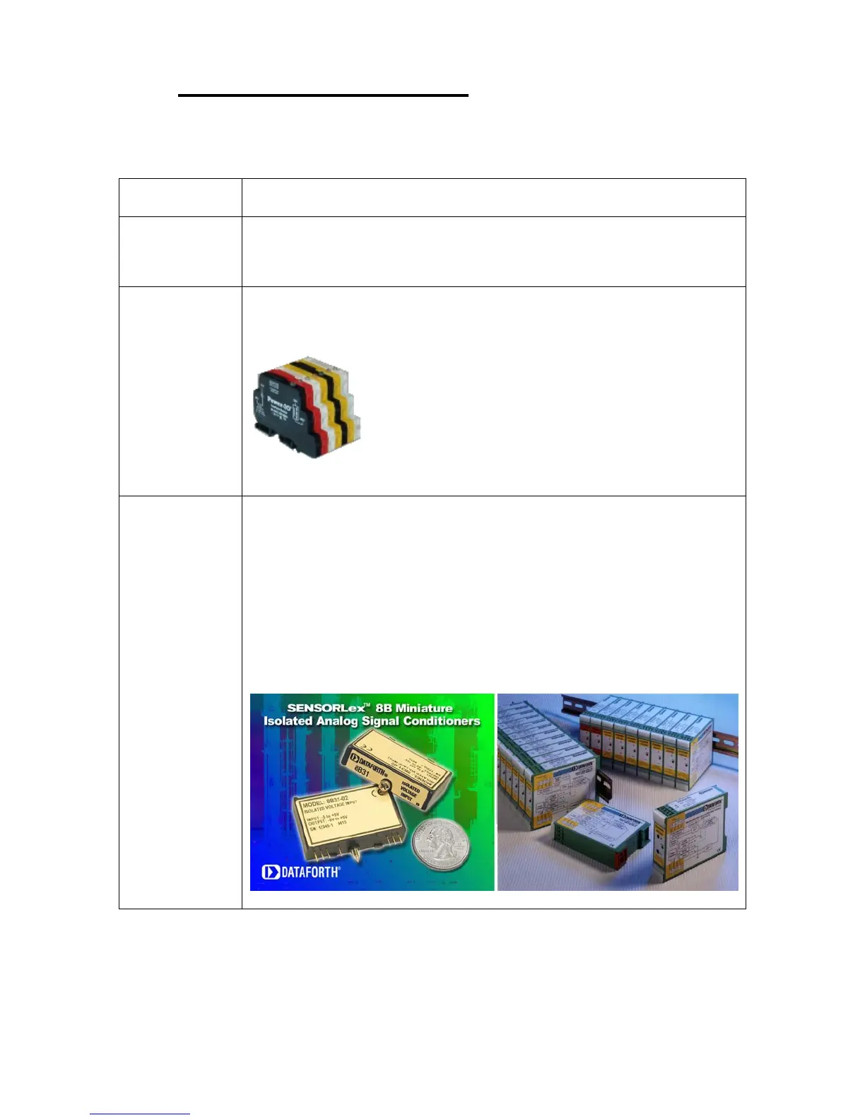
If isolation is desired, an external analog-to-analog isolation module may be
used. (eg. Dataforth Sensorlex
®
8B series or DSCA series modules.)