7
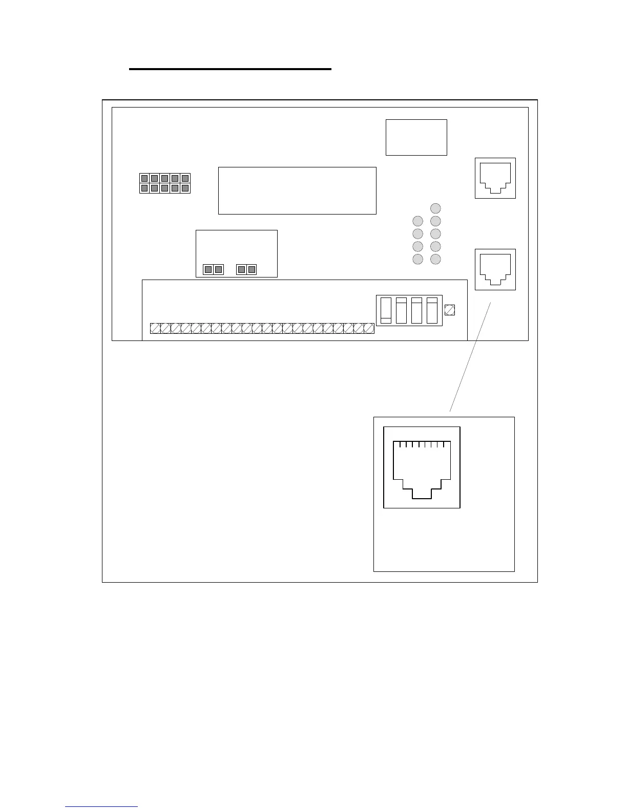
4 ELECTRICAL INTERFACE
Hookup Wiring Diagram:
SERIAL
PORT
ETHERNET
PORT
SETUP
RUN RS-485
RS-232
120
OHM
TERM.
NO
TERM.
BACK
LIGHT
ON
BACK
LIGHT
OFF
FLASH PROGRAMMING HEADER
(INTERNAL)
################
################
M2-RX
M2-TX
M1-RX
M1-TX
DCD
XMT
RxD
TxD
PWR
JP1 JP2
ETHERNET
SERIAL
LCD DISPLAY
1 2 3 4 5 6 7 8 9 10 11 12 13 14 15 16 17 18 19 20 21 22
LCD ADJ
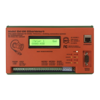
EtherMeter™ AMR-Industrial Interface
scadametrics.com
ETHERMETER-100
PATENT PENDING
MAC ID:
00-1D-C8-nn-nn-nn
PWR+
PWR-
CANH
CANL
RESERVED
AIN1+
AIN1-
AIN2+
AIN2-
AUX1+
AUX1-
AUX2+
AUX2-
M1-TX
M1-RX
M1-CMN
M2-TX
M2-RX
M2-CMN
485-A
485-B
485-CMN
AIN1:
ON=4-20mA
OFF=0-5V
AIN2:
ON=4-20mA
OFF=0-5V
(INTERNAL)
PRODUCT/MAC ID LABEL
SERIAL
PORT
1 2 3 4 5 6 7 8
1 RI (UNUSED)
2 DCD (CAN ALSO FUNCTION AS CTS)
3 DTR (TIED TO V+)
4SIGNAL GND
5RxD
6TxD
7 CTS (UNUSED)
8RTS
SERIAL PORT
EXPLODED VIEW
POWER AND GROUNDING NOTES:
1. The EtherMeter requires a 9-36 VDC Power Supply (2.50 W Max). It is recommended
that the common of the DC power supply be bonded to earth ground.
2. All connected communication equipment must utilize the same ground reference. To
achieve this, a low-impedance ground bus wire should be tied to the DC common of each
connected communication device.