32
In the previous illustration, wiring is shown for Analog Input Channel #1, although the principles
are the same for Analog Input Channel #2.
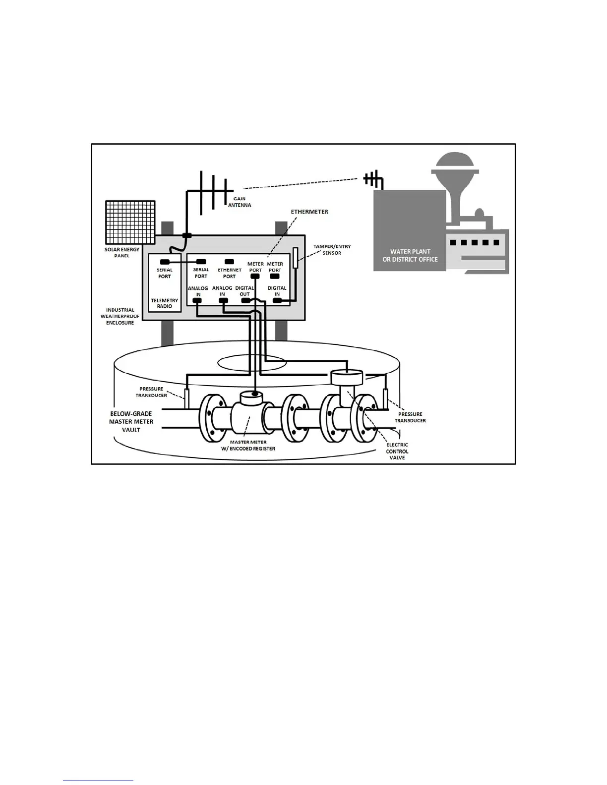
The following diagram is an example of an EtherMeter deployed as a standalone RTU. Note the
use of the auxiliary I/O to provide ON/OFF signaling and analog input monitoring, in addition to
monitoring one (or two) meter registers.