11
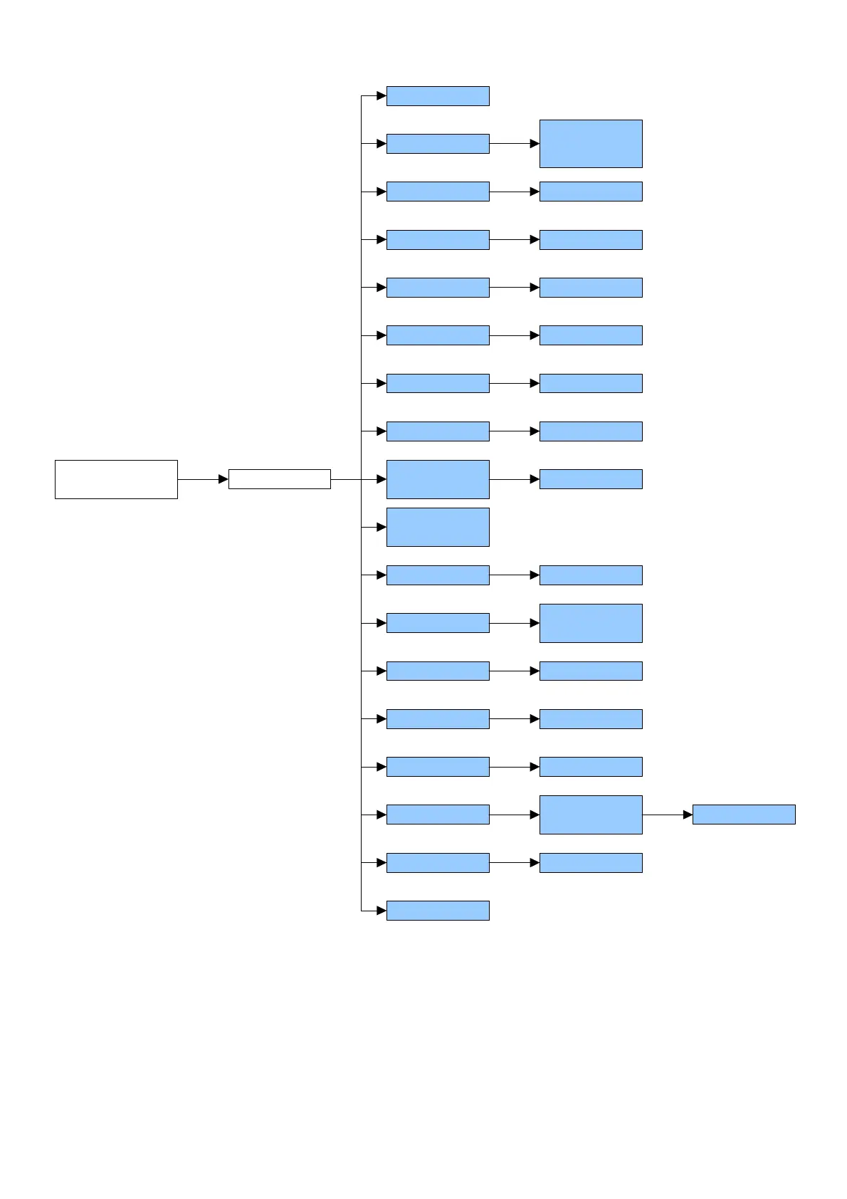
SET-UP ENVIRONMENT BLOCK DIAGRAM
SETUP
ENVIRONMENT
F0 CAL
F2 Unit
F3 CAPA
F4 Point
F1 rES
F5 Point
F6 init ZEro
F9 A-D
COUNTS
F8 SCSIUE
TARE
0, 1, 2, 3, 4
F10 SPEED 7.5, 15, 30, 60
F11 BAUD
Pin
1 3000,
1 6000,
dUaL rAnGE
kiLoS, 100
3, 6, 15, 30
0, 1, 2
0 … 20
On, oFF
F12 Min Coin
F13 SEriES
1, 2, 5, 10
On, oFF
F7 rE ZEro 0 … 20
F17 rESEt
2400, 4800,
9600, 19200
F14 Point
F15 LAnG
F16 GrU
FiXED, FLoAt
En, it, ES,
Fr, DE
XXX
9,XXXXX
In the parameter description:
- The METRIC parameters are shown with the (*) symbol, and, with approved instrument, these are read only. See
section 9.
“F0” - CALIBRATION (*)
Premise: The unit of measure of the calibration is fixed at kilogram (“kg”).
1) The displays show “CAL F0”: press the TARE key to get into the step.
2) The displays show the acceleration value set in the F16 step: enter the gravitational acceleration value of the
calibration zone if different from the use zone and press the TARE key to confirm; one must modify all the 6 digits
of the gravitational acceleration. The value will be set also in the F16 step.