General system description 2 - 5
Doc.nr : Rc400-Manuale_v20_e.doc
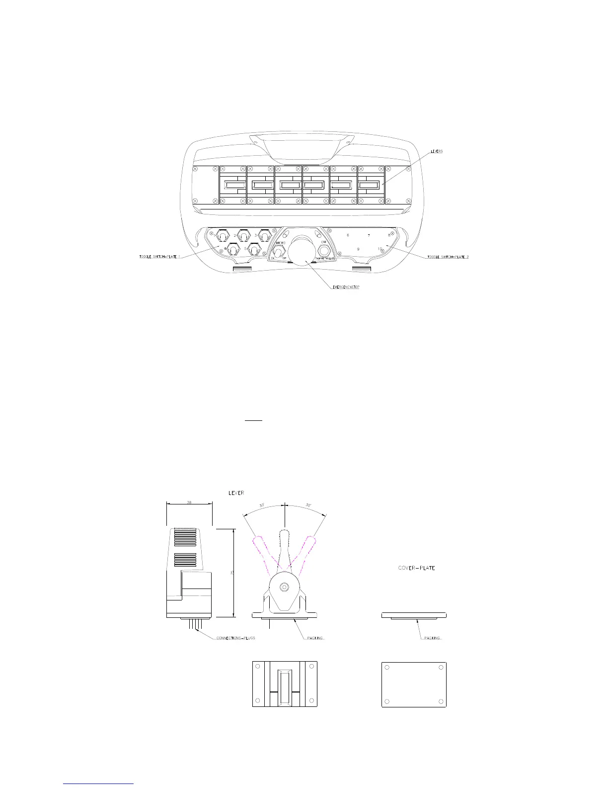
A brief description is given now of the component parts of the control unit.
The control unit is comprised of manouevre levers for proportional control, switches for
ON/OFF and function changing, micro-operation and emergency stop. ( See separate headings
below ).
Manoeuvre levers.
The manoeuvre levers give fully variable proportional operation and are sprung loaded to
return to zero position, i.e. "dead-man's-handle". When the manoeuvre levers are moved from
zero position the respective hydraulic function starts to operate slowly and increases in speed
as the lever is moved further from zero position and vice versa as the lever is moved back
towards zero position. If any levers are not included for a particular installation, a cover plate
can be mounted for the unused lever locations.
( See also title " Micro-speed control " ).
For safety reasons all manoeuvre levers must be in their zero/neutral positions for a start-up to be made. If any
lever is not in its zero / neutral position during start-up, the control unit will blink and beep the same number of
times as the number of the lever to indicate which manoeuvre lever is faulty. The control unit can be used but the
faulty lever will be locked and disengaged. ( For example if it beeps and blinks five (5) times, it is the 5th lever
from the LEFT which is faulty or giving the problem signal ).

 Loading...

