General system description 2 - 9
Doc.nr : Rc400-Manuale_v20_e.doc
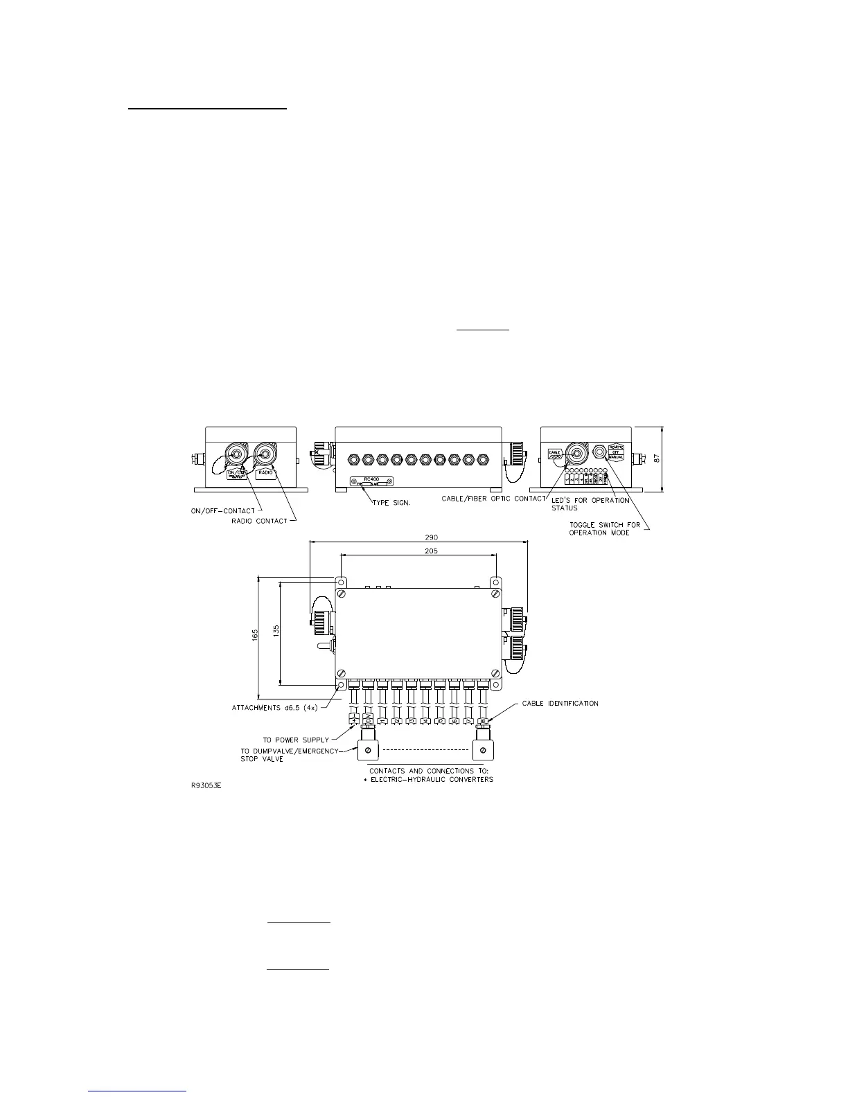
5. ELECTRONICBOX.
The electronicbox is manufactured in aluminium and is provided with attachments and contacts
for connection to the portable control unit, radio receiver box and ON/OFF functions. There are
also connections and contacts for supply voltage, electro-hydraulic converter valves, slide
controls and dump valve. Since the electronicbox can be exposed to very tough environments,
the box is encapsulated to give protection from damp, heat, cold, dust, vibration and corrosive
environments.
The electronicbox has short circuit proof inputs and outputs and has protection against polarity
reversal, over-voltage and large incoming voltage transients and EMC / RF. Connection of the
electronicbox can therefore be made without risk of damage. The electronicbox is delivered for
supply voltages of +12 / +24 VDC ( +/- 20 % ) with negative ground. There are two standard car
type fuses located inside the electronicbox.
Plus fuse: + 10 Amp. and minus fuse: - 30 Amp.
A transformer for standard mains voltages can also be used to provide the electronicbox with supply voltage.
Primary voltage: 110, 115, 220-240, 380, 440 VAC and secondary voltage + 12 / +24 VDC ( +/- 10%).
There are LEDs on the electronicbox to indicate operating status e.t.c : See also page : 5-2 !!!
POWER: Indicates supply voltage to the electronicbox ( toggleswitch in REMOTE position ).
DV: Dump-Valve activated.
ON/OFF: ON/OFF function activated. The LED is commoned and summed, i.e. only one switch at a time can
be activated from the control unit to enable control.
DIR. A: Manoeuvre lever A-direction activated and moved . The intensity of the light from LED-A increases
with increased lever angle. The LED is commoned and summed, i.e. only one manoeuvre lever at a time
can be manoeuvred in the A-direction to enable control.
DIR. B: Manoeuvre lever B-direction activated and moved . The intensity of the light from LED-B increases
with increased lever angle. The LED is commoned and summed, i.e. only one manoeuvre lever at a time
can be manoeuvred, in the B-direction to enable control.

 Loading...

