8
RETURN TO TABLE
OF CONTENTS
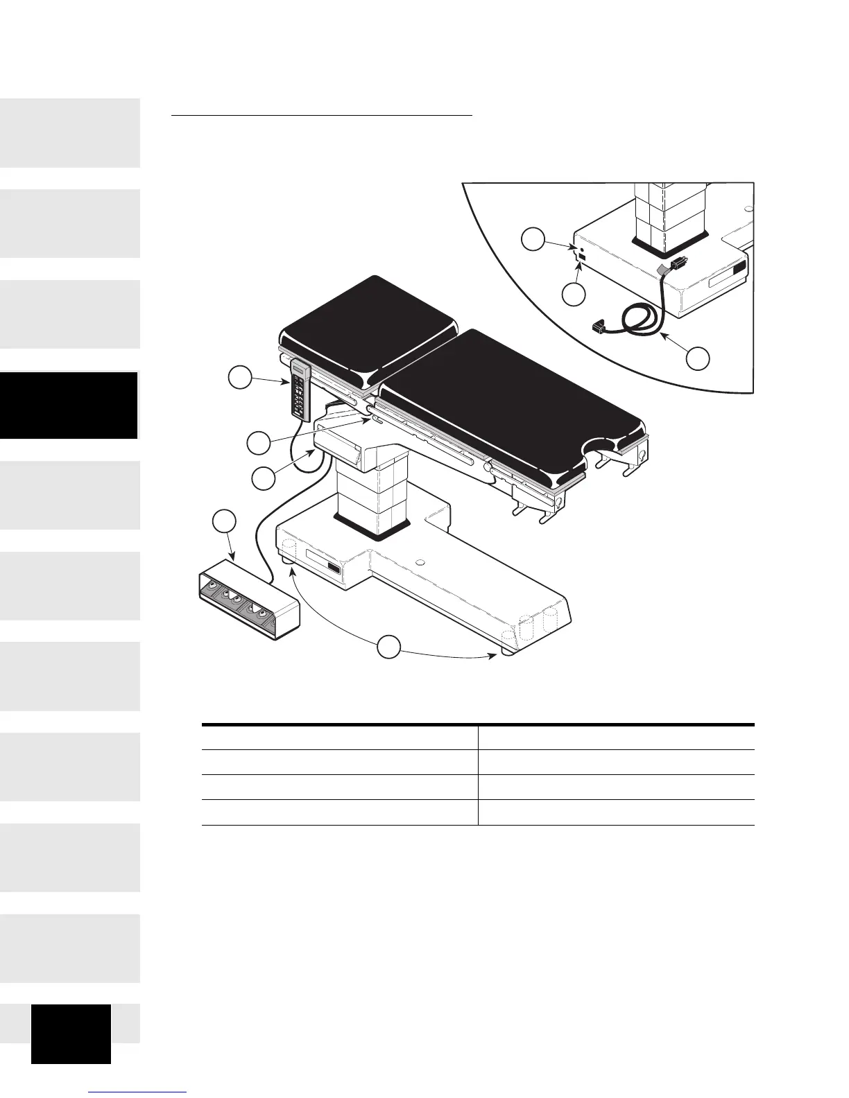
COMPONENTS OVERVIEW
The illustration below shows the location of the table’s major components and
the chart below provides their descriptive name.
DESCRIPTION OF COMPONENTS (Basic Table)
1. Hand Control 5. Line Power Pilot Lamp
2. Foot Control (Optional) 6. Plug Receptacle
3. Emergency Override Panel 7. Power Cord
4. Floor Lock Cylinders 8. Latch Handle(s)
CA800300
OMI
7300
OMI
7300
1
2
3
4
5
6
7
8
LEVEL
UNLO
CK
ENABLE
LOCK
DISABLE
7100
OMI
Component
Overview