www.scheppach.com / service@scheppach.com / +(49)-08223-4002-99 / +(49)-08223-4002-58
GB
|
31
• When dismantling, pull the clamping lever (K) up-
wards and remove the parallel stop (5).
• The clamping force of the parallel stop can be ad-
justed at the rear knurled nut (P).
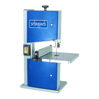
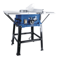
8.5 Adjusting the cutting width (Fig. 8 + 8.1)
• The parallel stop (5) must be used when cutting
• Place the parallel stop (5) on the guide rail (Q) to
the left or right of the sawing blade
• 2 scales (L/M) are printed on the guide rail for the
parallel stop (5), which show the distance between
the stop rail and sawing blade.
• Adjust the parallel stop (5) to the required dimen-
sion in the window (O) and use the clamping lever
8.6 Using the table width enlargement (Fig. 9 - 10)
•
• Loosen the clamping lever (8) and pull the table width
enlargement out far enough so that the workpiece to
be sawn can lie on it without tipping. (Fig. 10)
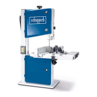
8.7 Sawblade changing(Fig. 11 + 12)
• Attention: Pull the mains plug!
• Attention! Wear protective gloves when changing
• Remove the parallel stop and the table width en-
largement in reverse order (Fig. 7-8).
• Open the top and bottom of the housing door.
Open the door locks (2) using a slotted screwdriv-
• Relieve the saw band tension with the clamping
screw (11), remove the band. Fig. 11
• Remove the tape. Remove the saw band from the
saw band rollers and through the slot in the saw
table (7).
• Put on a new saw band. Place the new saw band
in the middle of the two saw band rollers. The teeth
of the saw band must face down towards the saw
table.
Side correction (Fig. 11)
• The sawblade should run in the centre of the band
wheels.
•
of the handle (J).
• Attention! The saw band should run over the cen-
tre of the band wheel after multiple turns. Visual
inspection!
• -
tension screw (11). The degree of tensioning de-
pends on the sawblade width. Wide sawblades
must be tensioned more than narrow ones.
•
• Attention: Too strong a tensioning will cause pre-
mature breaking.
• Fit the table width enlargement in reverse order.
(Fig. 7-7.4)
•
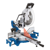
8.8 Setting the number of revolutions
(Fig. 12 + 13 + 13.1)
Pull the mains plug!
• Open lower guard. The table top has to be tilted
• Release the belt with the tension handle (12).
• Put the belt into the desired position. (S1 or S2).
• Retension the belt with the tension handle (12).
•
Rpm range:
Rpm stage 660 m/min.
For processing hardwood, materials similar to
Rpm stage 960 m/min.
8.9 Sawblade guiding (Fig. 14)
button (13).
The upper sawblade guiding can be set from 0 to 175
mm work piece height.
A clearance as small as possible to the work piece
ensures an optimum sawblade guiding and safe
working.
Back pressure bearings (Fig. 15+16)
The back pressure bearings (e) accept the feed pres-
sure of the work piece. Set the upper and lower back
-
es the sawblade back. Tighten the screws (g). The
distance should be 0.5 mm.
Upper guide rollers (Fig. 15)
Set the upper guide rollers (f) to the corresponding
sawblade width. The front edges of the guide roll-
ers must not exceed the tooth base of the sawblade.
tighten the screws (g).
Lower guide rollers (Fig. 16)
Set the lower guide rollers (i) to the corresponding
sawblade width. The front edges of the guide roll-
ers must not exceed the tooth base of the sawblade.
tighten the screws (h).
 Loading...