english 23
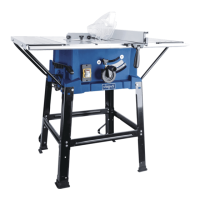
Sawblade - riving knife
Fig. "L"
1 holding rnandrel
2 left-handed hex. nut
•Takeoutthelefthandtableinlay.
•Inserttheholdingmandrel(1)intothesawspindleviathe
bore in the right- hand side of the table. For releasing or
tighteningthehex.nutM20(2) the saw spindle is locked
with the holding mandrel.
•Note the sawblade running direction.
Riving knife
• Releasethescrew(3),insertandclampintherivingknife.
The distance between the sawblade and the riving knife (4)
must amount to no more than 8 mm and must be checked
each time the sawblade is changed and reset as necessary.
The riving knife tip must never be set lower than the height
ofthebaseofthetopmostsawtooth.Asettingtornax.2 rnrn
under the topmost sawtooth tip is ideal.
The riving knife is an irnportant safety device, which guides the
workpiece and prevents the cut pinching and the workpiece
being thrown backwards. Note the riving knife thickness - refer
to the nurnbers starnped on the riving knife. The riving knife
must not be thinner than the sawblade body and not thicker than
its cutting joint width.
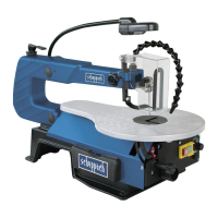
Attention! Close the protection cap (5)
Risk of damage!
Suction hose
Fig. "L1"
attachsuctionhoseØ50andafxhosebandclip
Suction connection piece
Placethesuctionconnectionpieceforthedustextractoronto
the back emission tube
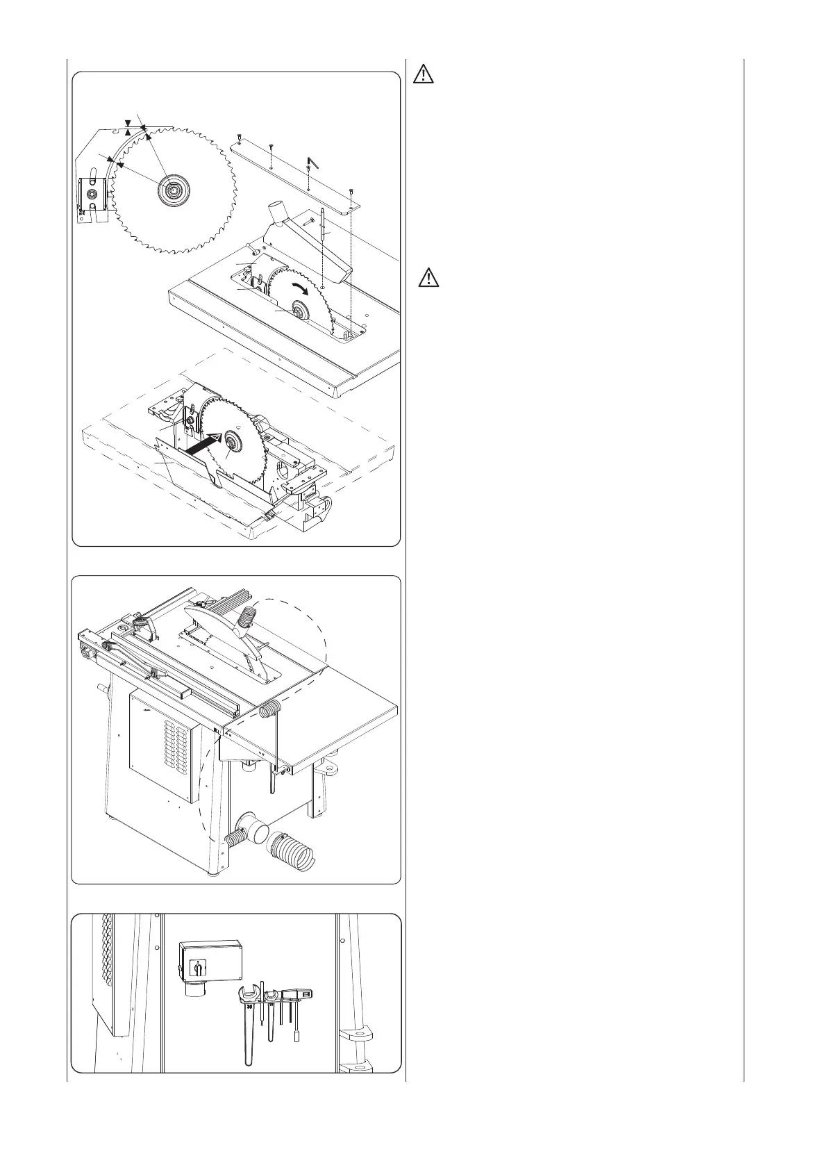
Tool holder
Fig. "M"
Placethesuppliedtoolsforthets 4010 within easy reach in
the tool holder.
Fig."L1"
Fig."M"
Fig."L"
3
2
1
3
2
4
5
2mm
3-8mm
3-8mm