INSTALLATION AND COMMISSIONING
30.30.01.00956/01 www.schmalz.com EN | 15
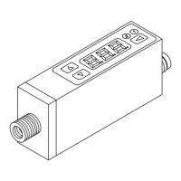
4.2.1 Pin assignment, M8 connector /M12 connector
1)
when using a Schmalz connection line (see accessories)
4.3 IO-Link commissioning
When operating the switch in IO-link mode (digital communication), the supply voltage, Gnd and the
C/Q communication cable must be directly connected with the corresponding connectors of an IO-Link
master with Ports IO-Link Class A. When doing so, a new port must be used for each switch; a
junction of several C/Q cables is not possible with only one IO-Link master port.
The IO-Link master must be connected in the configuration of the automation system in the same way
as other fieldbus components. To activate the port for IO-link communication, a software tool from the
respective master manufacturer is usually provided (e.g. Siemens PCT Beckhoff TwinCAT, etc.). The
necessary device description data (IODD) for the switch can be downloaded from our website
www.schmalz.com.

 Loading...