EasyManua.ls Logo

schmersal PROTECT-PSC - Page 36

schmersal PROTECT-PSC
267 pages
Print Icon
To Next Page IconTo Next Page
To Previous Page IconTo Previous Page
Loading...
3
Instruction Manual PROTECT-PSC
V 2.6R01 / 04.19
34
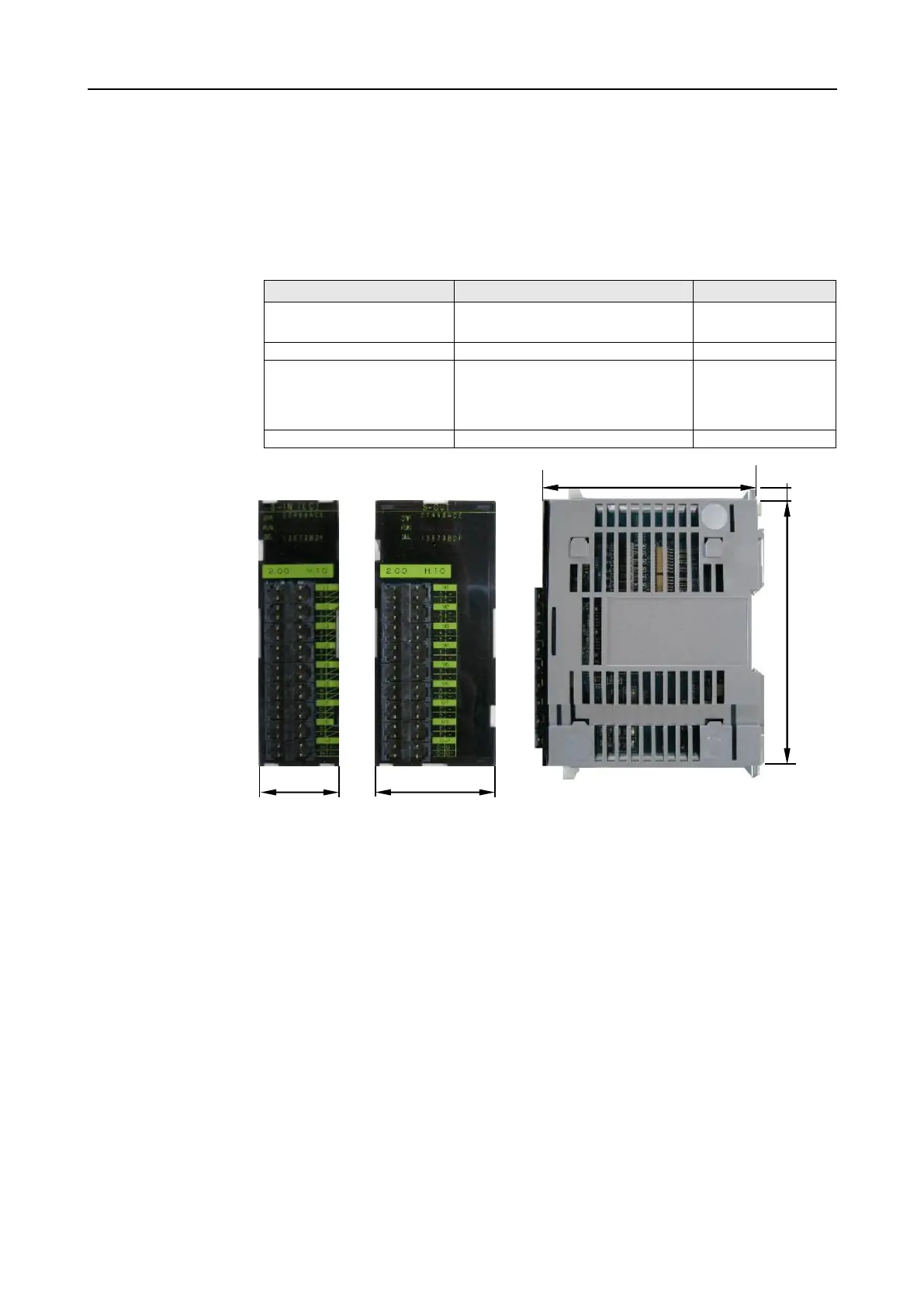
3.1.2 Basic module structure
All modules have a plastic housing made of PPE. Depending on version their
overall width differs (30mm / 45mm).There is a plug on the reverse side for the
electrical connection to the back plane BUS and the slots for mechanical fixing.
The front area is subdivided into a display area and a connection/operating area.
The modules have different colour markings for faster identification.
Module type
Model
Marking
Master module
PSC-CPU-OP-MON, PSC-CPU-
MON
green
Sub-Master module
PSC-SUB-MON
green
E/A module
PSC-S-STP-E, PSC-S-STP-LC,
PSC-S-STP-ELC, PSC-S-IN-E,
PSC-S-IN-LC,
PSC-S-OUT, PSC-S-Relais
yellow
Operational I/O modules
PSC-NS-IN, PSC-NS-OUT+
gray
T
T
a
a
b
b
l
l
e
e
3
3
-
-
2
2
C
C
o
o
l
l
o
o
u
u
r
r
m
m
a
a
r
r
k
k
i
i
n
n
g
g
o
o
f
f
t
t
h
h
e
e
m
m
o
o
d
d
u
u
l
l
e
e
s
s
F
F
i
i
g
g
u
u
r
r
e
e
3
3
-
-
1
1
B
B
a
a
s
s
i
i
c
c
m
m
o
o
d
d
u
u
l
l
e
e
s
s
t
t
r
r
u
u
c
c
t
t
u
u
r
r
e
e
Display area for:
Status of the inputs/outputs
Error messages
Communication
Connection area for:
Sensors, actuators
Power supply
Possible additional operating units
Module width
30mm
45mm
45mm
30mm
80mm
100mm
8
80mm
100mm
10mm

Table of Contents