EasyManua.ls Logo

schmersal PROTECT-PSC - Output modules

schmersal PROTECT-PSC
267 pages
Print Icon
To Next Page IconTo Next Page
To Previous Page IconTo Previous Page
Loading...
3
Instruction Manual PROTECT-PSC
V 2.6R01 / 04.19
345
3.9 Output modules
3.9.1 General description
All output modules are self-monitoring and comply with PL e, Category 4 to
ISO 13849-1 (the overall category will depend on the external circuitry).
The outputs may be parameterised as one or two channel using PROTECT-
PSCsw.
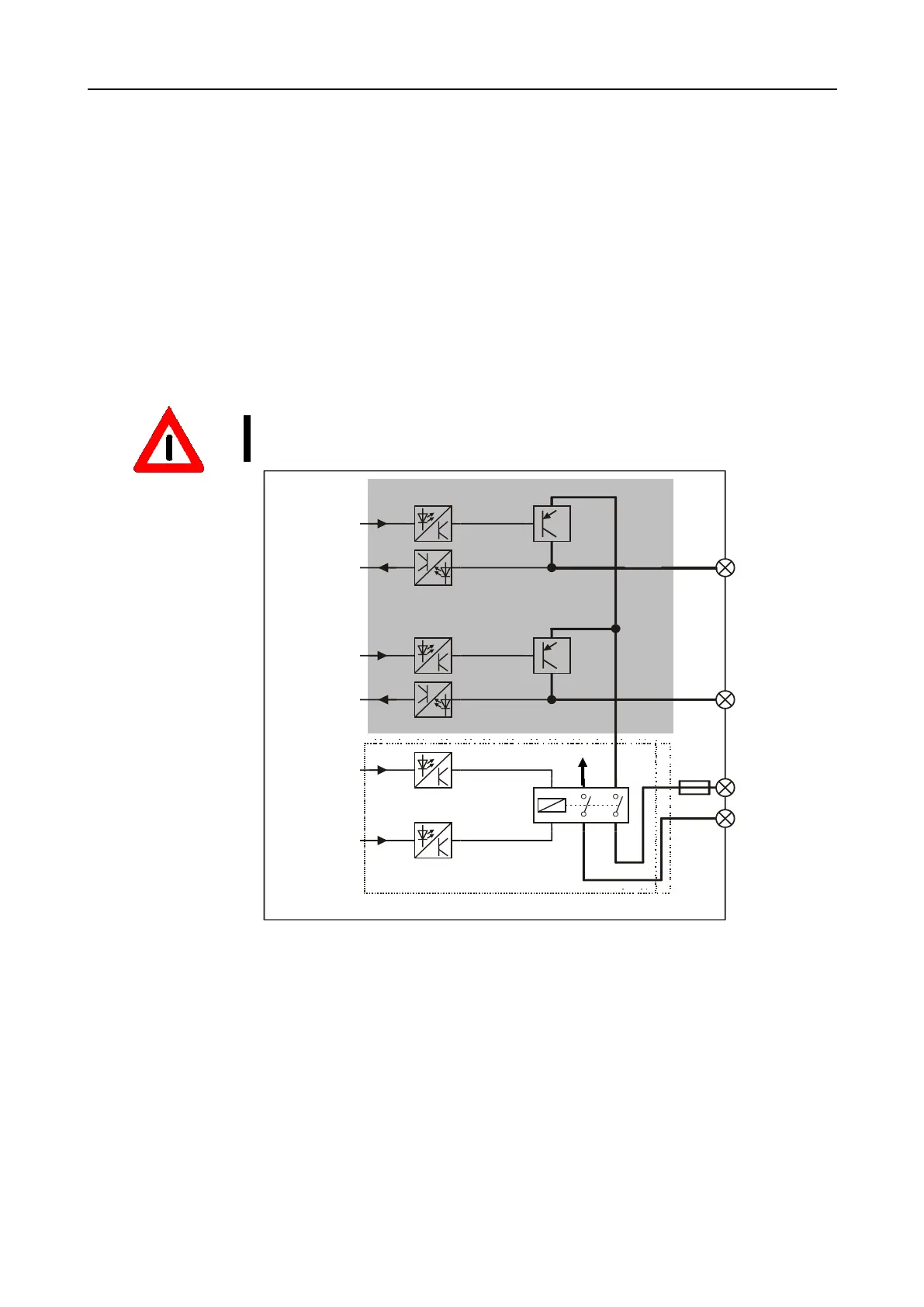
Basic circuit diagram for semi-conductor output
The diagram shows the basic structure of a semi-conductor output. The grey
shaded part of the circuit exists multiply depending on output module used.
Suitable protective measures (e.g. free-wheeling diode) are to be taken where
inductive loads are switched.
F
F
i
i
g
g
u
u
r
r
e
e
3
3
-
-
2
2
2
2
B
B
a
a
s
s
i
i
c
c
c
c
i
i
r
r
c
c
u
u
i
i
t
t
d
d
i
i
a
a
g
g
r
r
a
a
m
m
f
f
o
o
r
r
s
s
e
e
m
m
i
i
-
-
c
c
o
o
n
n
d
d
u
u
c
c
t
t
o
o
r
r
o
o
u
u
t
t
p
p
u
u
t
t
m
m
o
o
d
d
u
u
l
l
e
e
processor A
output 1
processor A
processor B
processor A
processor B
output 0
PWR+(24 VDC)
PWR-(0 VDC)
Channel 0
higher ranking relay level
processor B
Channel 1
F1
F1 = internal fuse (3.2A)

Table of Contents