EasyManua.ls Logo

schmersal PROTECT-PSC - PSC-Base

schmersal PROTECT-PSC
267 pages
Print Icon
To Next Page IconTo Next Page
To Previous Page IconTo Previous Page
Loading...
3
Instruction Manual PROTECT-PSC
V 2.6R01 / 04.19
326
3.6 PSC-Base
Technical data
Position
Description
Name
PSC-Base
Weight
5g
T
T
a
a
b
b
l
l
e
e
3
3
-
-
7
7
D
D
a
a
t
t
a
a
o
o
f
f
t
t
h
h
e
e
P
P
S
S
C
C
-
-
B
B
a
a
s
s
e
e
m
m
o
o
d
d
u
u
l
l
e
e
F
F
i
i
g
g
u
u
r
r
e
e
3
3
-
-
5
5
P
P
S
S
C
C
-
-
B
B
a
a
s
s
e
e
Backplane BUS
3.6.1 General description
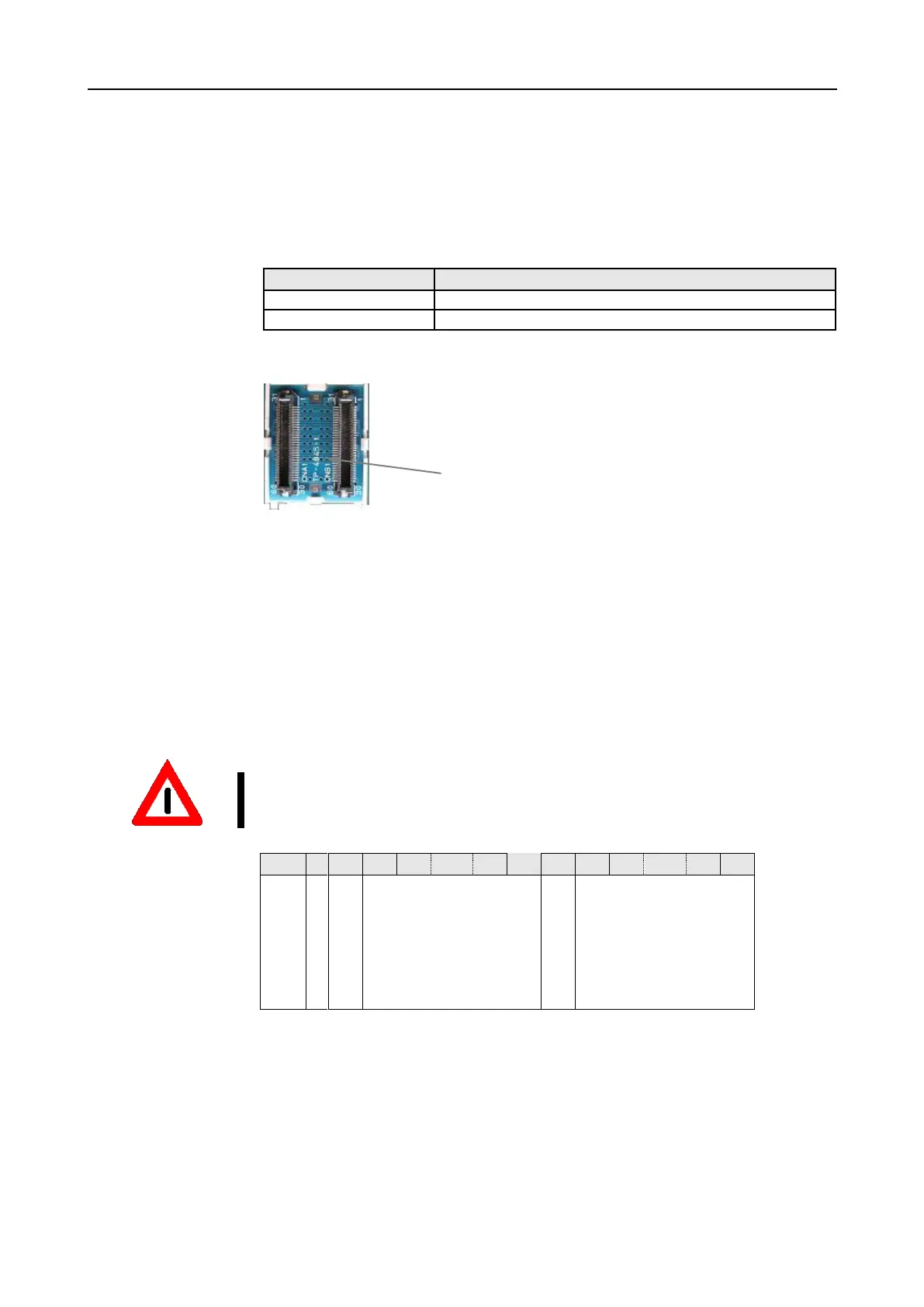
The PSC-Base module realises the back plane Bus.
The power module is always the far left module. The CPU is always located to the
right of it. I/O modules and operational I/O modules can then be positioned in any
order. It must be considered that the operational I/O modules must always be
placed to the right of the safe modules.
If 10 or more modules (including CPU) are used, a booster module must be posi-
tioned between slot 8 and slot 9.
Slot
-
0
1
2
7
8
-
9
10
14
15
Module
Power
CPU
Safe/operational
modules
Booster
Safe/operational
modules
Operational
modules
T
T
a
a
b
b
l
l
e
e
3
3
-
-
8
8
A
A
r
r
r
r
a
a
n
n
g
g
e
e
m
m
e
e
n
n
t
t
o
o
n
n
t
t
h
h
e
e
b
b
a
a
c
c
k
k
p
p
l
l
a
a
n
n
e
e
B
B
u
u
s
s

Table of Contents