EasyManua.ls Logo

schmersal PROTECT-PSC - PSC-CPU-MON; PSC-CPU-OP-MON

schmersal PROTECT-PSC
267 pages
Print Icon
To Next Page IconTo Next Page
To Previous Page IconTo Previous Page
Loading...
3
Instruction Manual PROTECT-PSC
V 2.6R01 / 04.19
327
3.7 PSC-CPU-MON / PSC-CPU-OP-MON
3.7.1 General description
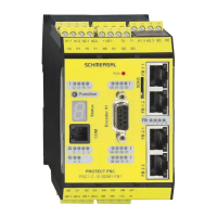
The CPU module is the central control unit of the PROTECT-PSC and is responsi-
ble for the following::
Executing the user program/FB firmware
Evaluating and controlling the safe and operational I/O modules
Monitoring power supply
Visualising status/error messages of the PROTECT-PSC
The version PSC-CPU-OP-MON has an additional battery enabling the operational
data (e.g. error protocol, data of the PN program, ….) to be maintained also if the
power is switched off (see Chapter 3.7.4 / 335).
Operating mode 3
If the PROTECT-PSC is in mode 3, the CPU module acts like a module with 4x2
inputs and 3x2 outputs.
Technical data
Position
Description
Name
PSC-CPU-MON / PSC-CPU-OP-MON
Operating voltage / current
24VDC+/-10% / 70 mA
Fusing
Internal fuse
Inputs: 3.2A
Outputs: 4.0A
Number of safety inputs
4x2 floating
Input resistence
Approx. 4.7 kΩ
Input current
5mA
High / low level
H: >18V / >3,5mA
L: <4,7V / <0,5mA
Minimum pulse duration for
possible detection
1.4ms (Input filter 0.7ms)
Minimum pulse duration for
safe detection
15ms
Number of safety outputs
3x2
Output current
Max. 0,5 A ohmic / output
Maximum switching voltage
24 VDC
Connecting plug
36-pin plug MORIMATSU M820A-09-xx
36-pin plug EMUDEN T7509-36-xx
Dimensions / weight
30 x 100 x 80 mm / (W/H/D) / 230g
T
T
a
a
b
b
l
l
e
e
3
3
-
-
9
9
T
T
e
e
c
c
h
h
n
n
i
i
c
c
a
a
l
l
d
d
a
a
t
t
a
a
P
P
S
S
C
C
-
-
C
C
P
P
U
U
-
-
M
M
O
O
N
N
/
/
P
P
S
S
C
C
-
-
C
C
P
P
U
U
-
-
O
O
P
P
-
-
M
M
O
O
N
N

Table of Contents