The pin no. 1 and 3 or 2 and 4 of the I-P or O-P connections are internally bridged
in order to facilitate the connection of the power supply to the neighbouring mod-
ule.
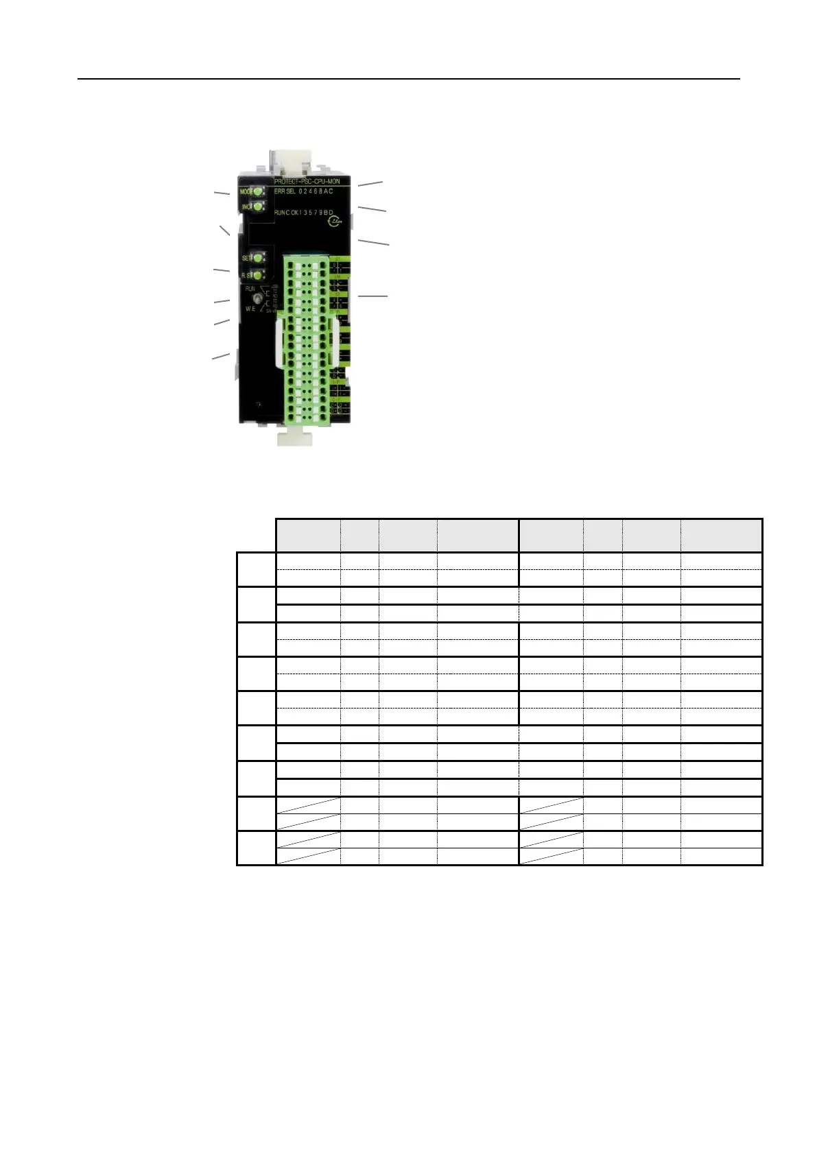
Status LED
ERR = on: Error / alarm
off: Operation
RUN = on : User program active
flashes: Initialisation phase
off: User program inactive
SEL = Always off
Display I/O
00h - 0Fh = Status of I/O
7 SEG LED
Terminal
00h - 0Fh = Connection sensor / actuator
I+, O+ = Power supply ( 24VDC)
I-, O- = Power supply (0VDC)
MODE/INC button
SET button
Restart button
RUN/W.E. button
Communication LEDs
Battery
 Loading...