EasyManua.ls Logo

schmersal PROTECT-PSC - Page 70

schmersal PROTECT-PSC
267 pages
Print Icon
To Next Page IconTo Next Page
To Previous Page IconTo Previous Page
Loading...
3
Instruction Manual PROTECT-PSC
V 2.6R01 / 04.19
338
3.7.6 Memory areas
The CPU module has different memory areas. Depending on the func-
tion/operation, the address is to be prefixed by a corresponding area specifier.
Chapter 6.10 describes which memory area is used for which function/operation.
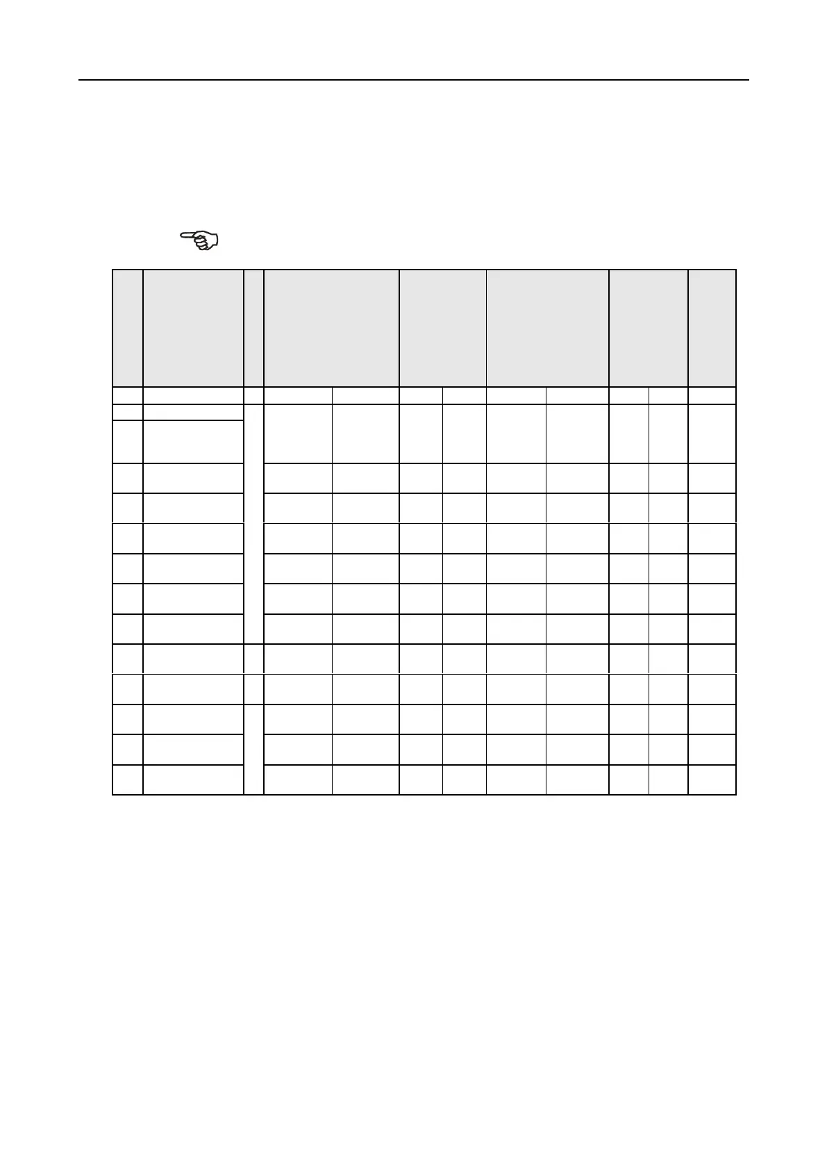
The following table provides an overview of the individual areas.
.
specifier
Use
Address range
BIT
address
Number of
BITs
WORD
address
Number of
WORDs
Data maintained
after switching
off
PS
PN
PS
PN
PS
PN
PS
PN
I/X
Input
BIT
I/Q000 -
I/Q0FF
(03FF)
X/Y400
X/Y4FF
(07FF)
256
(1024
)
256
(1024
)
I/Q00W -
I/Q0FW
(3FW)
X/Y40W
X/Y4FW
(7FW)
16
(64)
16
(64)
Q/Y
Output
M
Flag
M000 -
M7FF
M000 -
M7FF
2048
2048
M00W
M7FW
M00W -
M7FW
128
128
K
Hold flag
K000 -
K2FF
K000 -
K2FF
768
768
K00W
K2FW
K00W -
K2FW
48
48
X
V
Special flag
V000 -
V0FF
V000 -
V0FF
256
256
V00W -
V0FW
V00W -
V0FW
16
16
T/C
Timer
T000 -
T0FF
T/C000 -
T/C1FF
256
512
T00W
T0FW
T/C00W -
T/C1FW
16
32
L
Communication
L000 -
L7FF
L000 -
L7FF
2048
2048
L00W -
L7FW
L00W -
L7FW
128
128
P
Edge detection
P000
P1FF
P000
P1FF
512
512
P00W
P1FW
P00W
P1FW
32
32
EL
Data exchange
with gateways
EL000
EL3FF
EL400
ELBFF
1024
2048
EL00W-
EL3FW
EL40W-
ELBFW
64
128
EM
Data exchange
PS/PN
EM000
EM3FF
EM400
EM7FF
1024
1024
EM00W-
EM3FW
EM40W
EM7FW
64
64
D
Data register
WORD
D0000-0
D00FF-F
D0000 -0
D01FF-F
512
Byte
1024
Byte
D0000
D00FF
D0000
D01FF
256
512
X
N
Value register
N0000-0
N00FF-F
N0000-0
N01FF-F
512
Byte
1024
Byte
N0000
N00FF
N0000
N01FF
256
512
X
S
Special register
S0000-0
S03FF-F
S0000
S03FF
2048
Byte
2048
Byte
S0000
S03FF
S0000
S03FF
1024
1024
X
T
T
a
a
b
b
l
l
e
e
3
3
-
-
1
1
4
4
M
M
e
e
m
m
o
o
r
r
y
y
a
a
r
r
e
e
a
a
s
s
o
o
f
f
t
t
h
h
e
e
C
C
P
P
U
U
m
m
o
o
d
d
u
u
l
l
e
e
Input / output (I/X, Q/Y)
The address area I/Q000 to I/Q0FF is reserved for physical outputs. The address
area from I/Q100 to I/Q3FF, X/Y400 to X/Y7FF can be used for internal outputs
(software flag). Since the address assignment for inputs/outputs is provided from
the same memory area, assignments of the same addresses to inputs/outputs
such as I000/Q000, are not possible.
6.10 / 6-31

Table of Contents