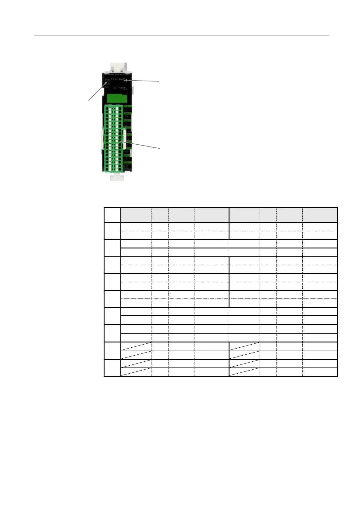
The pins no. 1 and 3 or 2 and 4 of the I-P or O-P connections are internally bridged
in order to facilitate the connection of the power supply to the neighbouring mod-
ules.
StatusLED
ERR = On: error / alarm
Off: operation
RUN = lights up: user program active
Off: user program inactive
SEL = Always off
Display I/O
00h - 0Fh = status of I/O
Terminal
00h - 0Fh = connection sensor / actuator
I+, O+ = power supply ( 24VDC)
I-, O- = power supply (0VDC)


 To Next Page