Assembly
24
02.00 | KHM | Assembly and Operating Manual | en | 389171
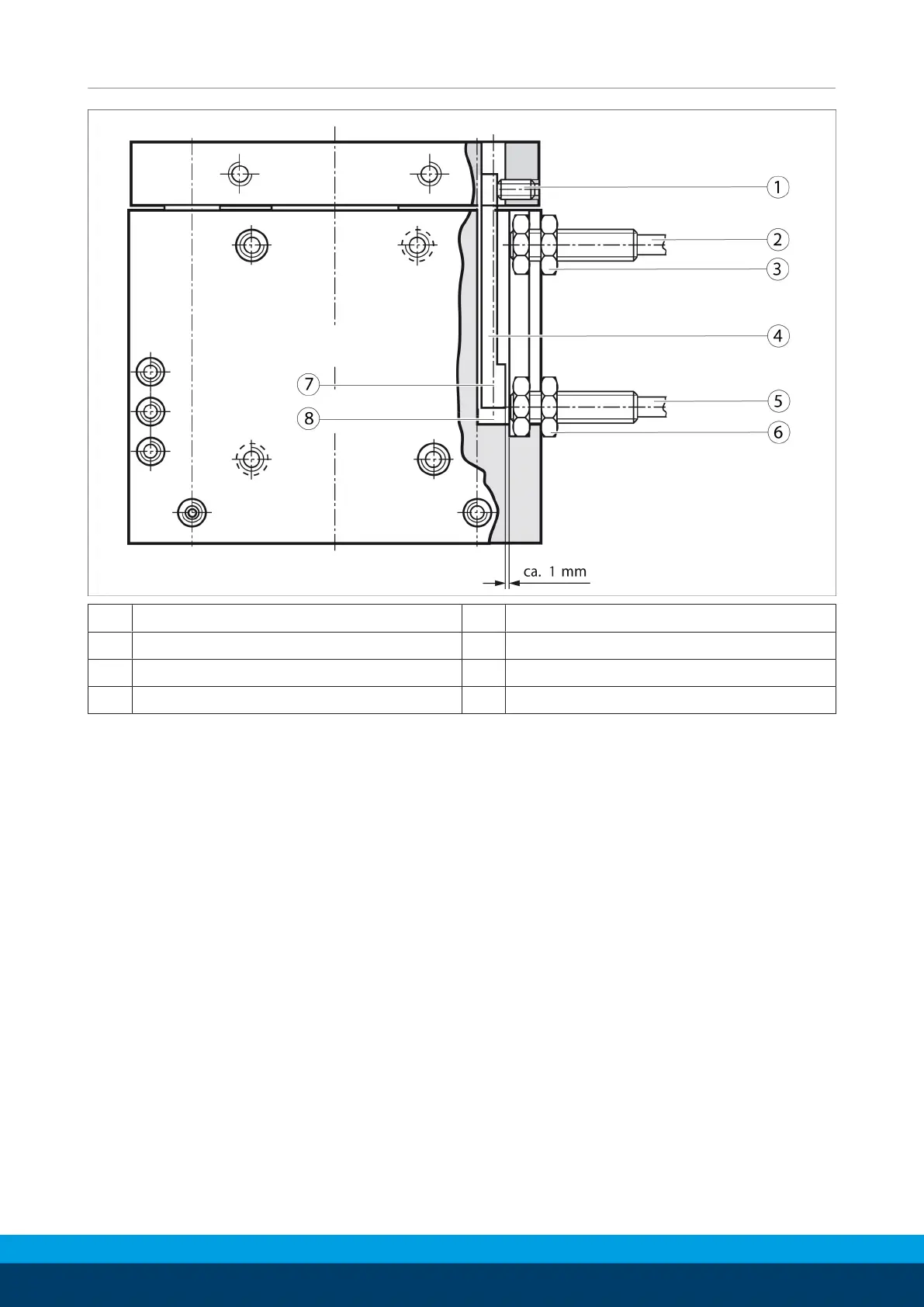
1 Attachment screw 5 Proximity switch
2 Proximity switch 6 Clamping nut
3 Clamping nut 7 Range of stroke 4 – 30 mm
4 Monitoring bolt 8 Range of stroke 14 – 40 mm
The KHM 40 linear unit requires two proiximty switches (closers).
The proximity swtiches are used to monitor the two end positions
(strokes from 4 ... 40mm).
Ø Set the linear unit to the »Up« position.
Ø Set the monitoring bolt onto the range of stroke of your choice.
To do so, undo the attachement screw in the lifting plate.
Ø Carefully install the proximity switch into the T-slot. The
proximity switches must not project further than the nut in the
T-Slot when installed.
Ø Fix the proyimity switches into place using the clamping nut.
Ø Undo the upper proximity switch and shift it to the desired
switching position.
Ø Carefully turn the proximity switch into the T-slot until it
touches the switching lug. Then turn back the proximity switch
by 1mm and attach it using the clamping nut.
Ø Move the linear unit to position »Down« and proceed in the
same way with the other proximity switch.
Ø Connect the proximity switch and test the function.