Assembly
04.00 | LGZ | Assembly and Operating Manual | en | 389192
19
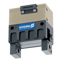
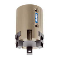
Mounting material (provided by customer)
Item Mounting 16 32 50
1 Rear module M3 x
max. 7,4
M4 x
max. 10
M8 x
max. 16
2 Module on the side M3 x
max. 7,4
M4 x
max. 10
M8 x
max. 16
3 Top jaws M3 x
max. 5
M4 x
max. 10
M8 x
max. 16
4 Centering pin Ø3 x max. 3 Ø5 x max. 5 Ø8 x max. 8
99 Centering sleeve Ø5h6 / 4,35 Ø5h6 / 4,35 Ø8h6 / 5,35
NOTE
• For mounting from the rear fix the module using the provided
centering pins (4).
• Mount the module using the mounting bores.
• Mount the top jaws using the mounting bores provided. Use
centering sleeves (99).
4.2 Pneumatic connection
WARNING
Risk of injury when machine/system moves unexpectedly!
• Switch off power supply before assembly and installation.
• Make sure that no residual energy remains in the system.
NOTICE
Damage to the gripper is possible!
If the maximum permissible finger weight or the permissible
mass moment of inertia of the fingers is exceeded, the gripper
can be damaged.
• A jaw movement always has to be without jerks and bounce.
• You must therefore implement sufficient reduction and/or
damping.
• Observe the diagrams and information in the catalog data
sheet.
 Loading...