36
Montage- und Betriebsanleitung für
2-Finger-Parallelgreifer Type PGN-plus
Assembly and Operating Manual for
2-Finger Parallel Gripper Type PGN-plus
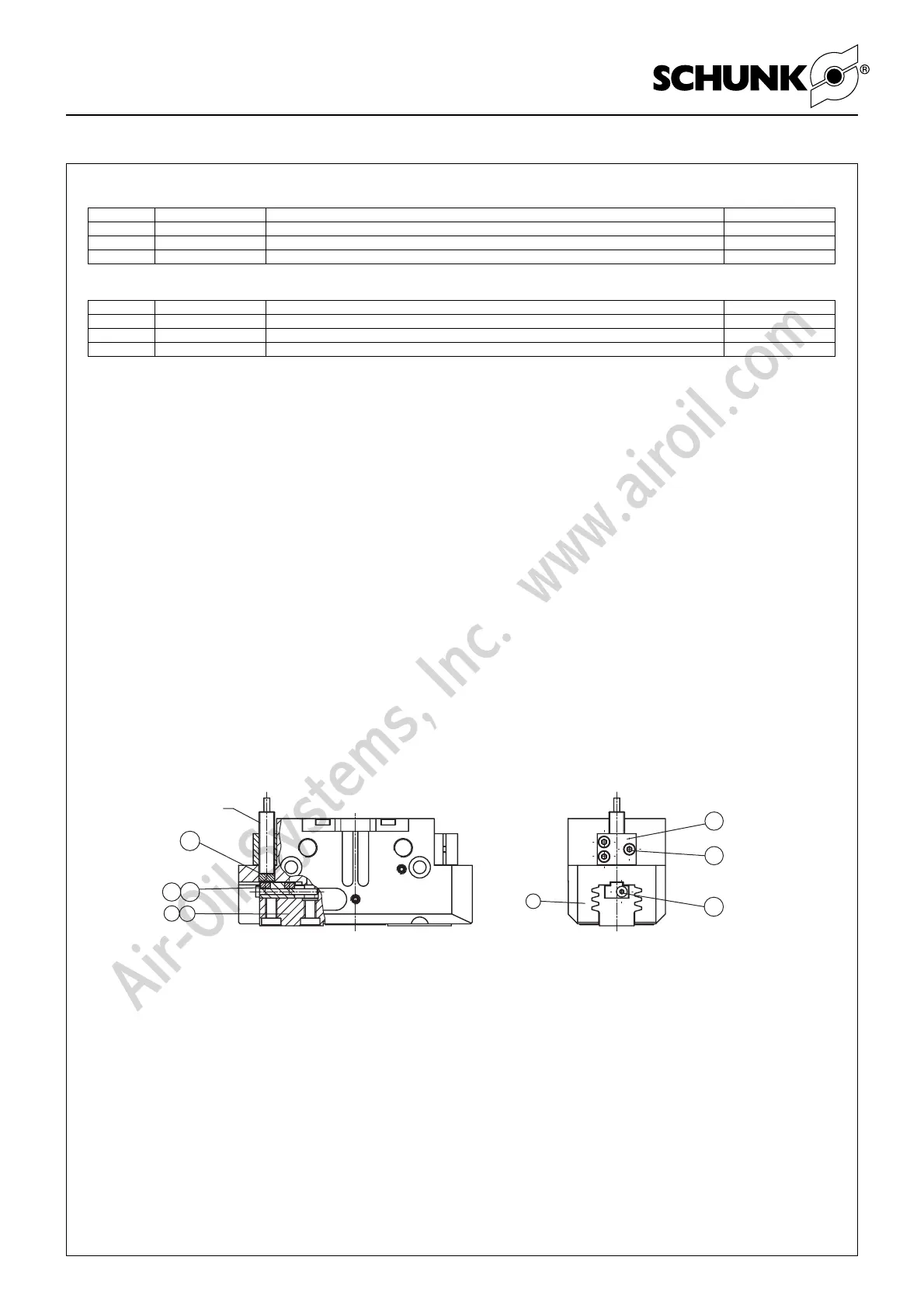
Montage des Anbausatzes
(Pos.-Nr. siehe Darstellung unten und Zusammenbauzeichnung
in Kapitel 9)
Bei der Version mit Staubabdeckung (Pos.-Nr. siehe Kapitel 9.2)
muss vorab der Dichtbolzen (Pos. 85) entfernt werden, um den
flexiblen Positionssensor FPS-M8 montieren zu können. Um die
Schaltnocke zu tauschen, muss vorab die Abdeckung (Pos. 81)
demontiert werden.
1. Entfernen Sie die Schaltnocke zur Abfrage mit induktivem
Näherungsschalter (Pos. 15) und die beiden Schrauben
(Pos. 42 und 43) aus der Grundbacke (Pos. 2 / 7).
2. Schieben Sie die Schaltnocke (Pos. 21 / 23) mit der
angefasten Seite vorraus in die Grundbacke (Pos. 2 / 7) und
schrauben Sie diese mit der dafür vorgesehenen Schraube
(Pos. 38) fest.
3. Schieben Sie zuerst die Distanzscheibe (Pos. 26) und dann
den flexiblen Positionssensor FPS-M 8 durch den
Klemmhalter (Pos. 17) in die dafür vorgesehene Bohrung des
Gehäuses (Pos. 1) auf Anschlag und Verklemmen Sie den
Sensor in dieser Position durch Anziehen der Schraube
(Pos. 18).
Assembling the mounting kit
(for item numbers see illustration below and assembly drawing in
chapter 9)
In the version with dust cover (see chapter 9.2 for item No.),
remove the sealing bolts (item 85) first, in order that the flexible
position sensor FPS-M8 can be mounted. The cover (item 81)
must be removed before the operating cam can be replaced.
1. Remove the operating cam for monitoring along with the
inductive proximity switch (item 15) and the two screws (item
42 and 43) from the base jaw (item 2 / 7).
2. With the chamfered side to the front, insert the operating cam
(item 21 / 23) into the base jaw (item 2 / 7) and screw it with
the screw provided (item 38).
3. First insert the spacer (item 26) and then flexible position sen-
sor FPS-M 8 through the bracket (item 17) into the special
hole drilled in the housing (item 1) to the stop, and clamp the
sensor in this position by tightening the screw
(item 18).
AS-PGN-plus 240/2 Ident-Nr. / Id. No. 301 644
Pos. / Item Ident-Nr. / Id. No. Bezeichnung / Description Menge / Quantity
21 5513 855 Schaltnocke / Control Cam 1
26 5512 312 Distanzscheibe / Spacer 1
38 9907 539 Schraube M4 x 40 / Screw M4 x 40 1
Pos. / Item Ident-Nr. / Id. No. Bezeichnung / Description Menge / Quantity
23 5512 311 Schaltnocke / Control Cam 1
26 5512 312 Distanzscheibe / Spacer 1
38 9907 900 Schraube M4 x 35 / Screw M4 x 35 1
AS-PGN-plus 300/2 Ident-Nr. / Id. No. 301 642
HINWEIS:
Technische Daten: siehe Katalog
Einstellung des Sensors Type FPS siehe seperate Bedienungs-
anleitung.
NOTE:
For technical data: see catalogue
For setting sensor type FPS, see separate user‘s manual.