10
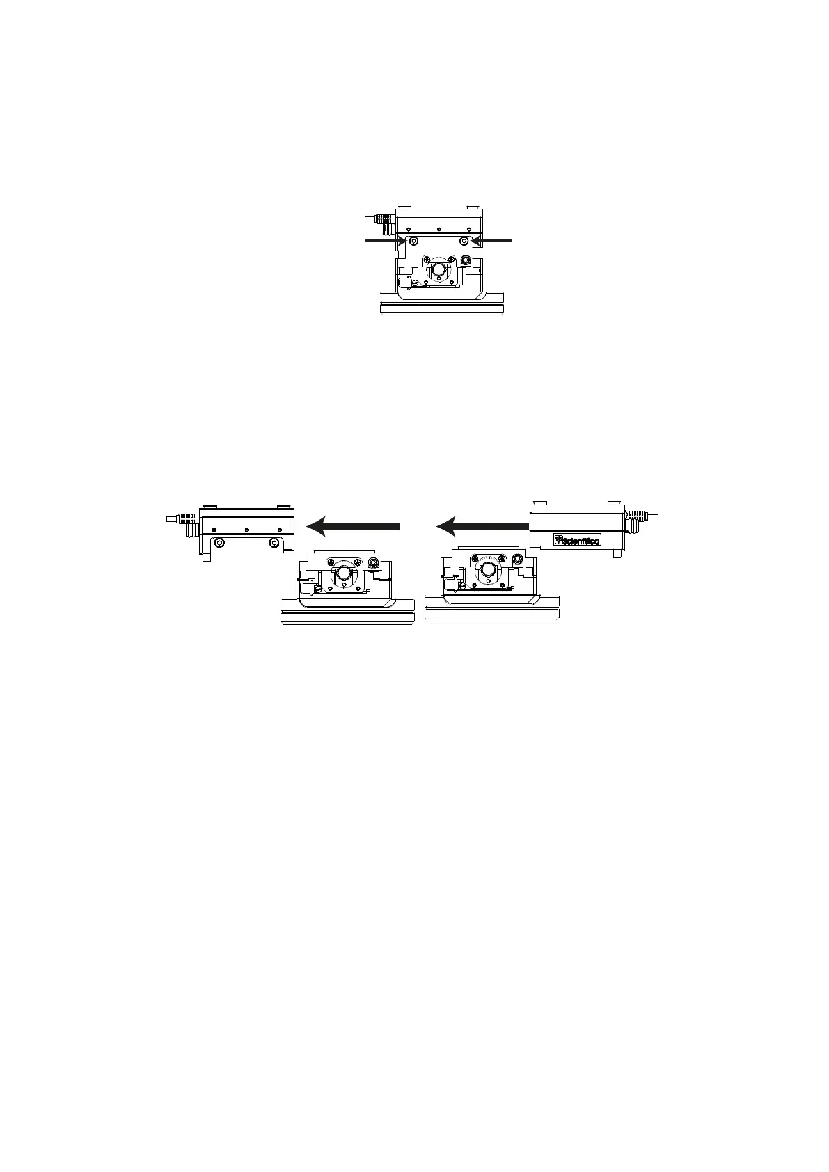
3. Loosen the dovetail screws on the X axis (blue)
Figure E: Rear view, indicating X axis (blue) dovetail screws
4. Remove the X axis (blue) from the Y axis (green) (1), turn the X axis through 180º
and slide it back onto the Y axis (2) so that the manual adjustment knob and cable
are positioned on the left side of the assembly when seen from the front.
Figure F: Rear view, removing, rotating and replacing the X axis (blue)
5. Retighten the X axis (blue) dovetail screws indicated in step 3
6. Position the lower half so that the green manual adjuster on the Y axis is furthest
away from you and the blue X axis adjuster is on the left hand side.
With the rotary stage facing you, slide the upper part of the PatchStar that was
removed in step 2 back onto the X axis (blue). Retighten the dovetail screws
indicated in step 1 on the lower part of the Z Axis L-bracket.
Slide
Rot ate and
Repla ce
1. 2.