UMT/WG T MT Rev3.0 – 08/10/2021 Pag. 3-EN
Contents
1 Introduction ....................................................................................................................................................................... 4
2 Safety issues with CO
2
- Safe handling ........................................................................................................................... 4
2.1 Precaution ................................................................................................................................................................. 4
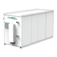
3 Unit description & Main components ............................................................................................................................. 6
4 Unit installation ................................................................................................................................................................. 7
5 Piping details ..................................................................................................................................................................... 8
5.1 Pipe Connections (Multi-Split) ................................................................................................................................ 8
5.2 Oil traps ..................................................................................................................................................................... 8
6 Test and inspection before start-up ............................................................................................................................... 9
6.1 Control of the unit tightness ................................................................................................................................... 9
6.2 Preliminary controls according to EN 60204-1, visual controls .......................................................................... 9
6.3 Management of the system. Configuration of the controllers ........................................................................... 9
6.4 Inspection of the water loop................................................................................................................................ 10
6.5 Earth connection ................................................................................................................................................... 10
7 Commissioning ............................................................................................................................................................... 11
7.1 Evacuation and pre-charge .................................................................................................................................. 11
7.1.1 “VACUUM”, SW function details ................................................................................................................... 11
7.2 Refrigerant & Oil Charging ................................................................................................................................... 12
7.2.1 Oil charge ....................................................................................................................................................... 12
7.2.2 Procedure for additional oil refill ................................................................................................................ 12
7.2.3 Estimation of the refrigerant charge .......................................................................................................... 13
7.2.4 Charging procedure ...................................................................................................................................... 15
8 User Interface and main Software features ................................................................................................................ 16
8.1 User Interface ........................................................................................................................................................ 16
8.2 On/Off unit ............................................................................................................................................................. 17
8.3 Regulation set point .............................................................................................................................................. 18
8.4 MPXPRO and ULTRACELLA/EVO CAREL configuration. .................................................................................... 19
8.5 MPXPRO and ULTRACELLA/EVO CAREL regulation ........................................................................................... 20
9 Serial Communication (PSD drivers, Evaporators and Supervisory System) .......................................................... 21
9.1 Communication with evaporators (features and requirements) .................................................................... 21
9.2 Serial connections and wirings ............................................................................................................................ 22
10 Recommended Annual Checks ..................................................................................................................................... 23
11 List of alarms .................................................................................................................................................................. 26
11.1 Hecu alarm............................................................................................................................................................. 26
11.2 PSD (Power+) alarm code ..................................................................................................................................... 31
11.3 PSD led status ........................................................................................................................................................ 33
12 Troubleshooting ............................................................................................................................................................. 34
13 Compressor Envelope ................................................................................................................................................... 34
14 Refrigerant drawing (P&I) .............................................................................................................................................. 36
15 HECU Controller layout ................................................................................................................................................. 37
16 Terminals blocks connection ........................................................................................................................................ 38
17 Dimensional drawing ..................................................................................................................................................... 38
18 General information and limits .................................................................................................................................... 39
19 Electrical details .............................................................................................................................................................. 39
20 Cooling capacity Table ................................................................................................................................................... 41
 Loading...