Do you have a question about the SCM CU 300C and is the answer not in the manual?
Provides an overview of the manual's purpose and scope for qualified technicians.
Details how to identify the machine using data punched on the metallic plate.
Provides contact information for SCM Assistance and Spare Parts Departments.
Offers general instructions, abbreviations, and information on enclosed documentation.
Explains various symbols used in the manual for clarity and safety.
Illustrates and explains warning signs and plates fixed on the machine.
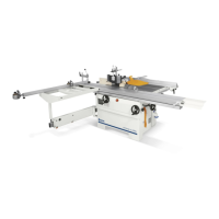
Describes the basic machine parts and features of the universal combined machine.
Defines the intended use of the machine and prohibited materials or operations.
Lists forbidden operations and potential misuse to ensure safe machine handling.
Identifies potential hazards that remain even when safety prescriptions are followed.
Emphasizes the compulsory training for machine operators on setup, operation, and safety.
Outlines essential safety regulations for machine operation and maintenance.
Details personal safety measures and required protective equipment for operators.
Provides crucial safety instructions related to machine operation and maintenance.
Specifies safety guidelines for fitting, using, and maintaining tools with the machine.
Ensures a safe working environment with proper lighting and clear access around the machine.
Highlights safety procedures to follow during maintenance operations.
Provides instructions for handling emergency situations like flooding, fire, or mechanical block.
Details procedures for safely removing, storing, or demolishing the machine.
Details the location and function of emergency stop buttons and related components.
Explains the various safety guards and accident-prevention devices installed on the machine.
Specifies the maximum and minimum dimensions for workpieces to be processed.
Provides detailed specifications for the saw and moulder units, including dimensions and power.
Lists the standard accessories included with the machine for various operations.
Lists optional accessories available for enhancing machine functionality.
Presents declared noise emission values for different operating conditions.
Provides dimensional drawings and specifications for the machine's overall size.
Illustrates the recommended safe working area around the machine and operator positions.
Provides instructions for safely unloading the machine using cranes or forklifts.
Details requirements for selecting a suitable, well-lit, and firm location for machine installation.
Procedure for safely fitting and replacing the saw blade, including necessary precautions.
Explains the critical steps for safely connecting the machine to the electrical system and grounding.
Details on connecting the machine to a dust extraction system for safety and efficiency.
Explains the function and use of various controls on the machine's control panel.
Details the location and operation of emergency stop buttons for immediate machine shutdown.
Lists essential checks and controls to perform before starting the machine.
Describes the correct procedures for starting and shutting down the machine safely.
Instructions for adjusting the riving knife to ensure proper saw blade clearance and safety.
Procedure for tilting the saw blade, including precautions for using dado sets.
Procedures for adjusting the scorer's height and alignment with the saw blade.
Guidelines for the correct and safe operation of the circular saw unit.
Details on adjusting the saw guard height for optimal protection during cuts.
Instructions for adjusting the splinter guard to trim it and ensure proper fit.
Guidance on using the telescopic ruler for 90° and inclined cuts, including stop positioning.
Procedure for setting the manual fence to zero for accurate parallel cuts.
Detailed instructions for operating the standard saw fence for parallel cuts.
Provides examples and steps for performing longitudinal cuts on panels.
Steps for adjusting the rule to perform oblique cuts, including telescopic extension use.
Procedure for adjusting planer knives for correct protrusion and proper surfacing.
Instructions for safely replacing planer knives, emphasizing proper sharpening and matching.
Guide for replacing the tips on the helicoidal planer cutterhead, including torque specifications.
Instructions for adjusting the inlet and outlet surfacing tables for precise planing.
Details on adjusting the fence for longitudinal shifting and tilting for various planing operations.
Detailed steps for fitting the mortiser unit, including table drive locking and lever adjustments.
Guidance on assembling spindle bits for both fixed and self-centering spindles, including safety notes.
Procedures for safe mortiser operation, including tool rotation, workpiece clamping, and guard positioning.
Procedure for adjusting the stroke of the additional table to limit slot depth for dead holes.
Method for adjusting slot width by marking and testing transversal stroke.
Steps for preparing the machine to transition from planing to thicknessing operations.
Procedure for adjusting thicknessing tables using manual lifting for proper operation.
Guide for manually adjusting the thicknessing table for desired stock removal.
Procedure for adjusting the spring pressure of feed rollers for optimal workpiece feeding.
Details on safety guards for thicknessing, including anti-kickback fingers and general safety warnings.
Instructions for adjusting planer knives for uniform wear and quality finish.
Guide for replacing helicoidal planer tips, ensuring proper seating and torque.
Instructions for adjusting the spindle height to the worktable, ensuring the tool is correctly positioned.
Guidance on selecting the appropriate spindle speed based on tool, wood, and working type.
Details on using the tenoning table for milling operations, including depth and slot adjustments.
Information on adjusting the hood-fence unit for various profiling operations and safety considerations.
Steps for adjusting the spindle moulder hood guide for moulding without needing to remove it.
Illustrates working examples for profiling operations using the spindle moulder.
Description and adjustment procedures for the cutterblock guard during surfacing operations.
Essential safety procedures for planing operations, including workpiece handling and guard use.
Specific safety procedures for surfacing workpieces thinner than 75 mm using the planer.
Instructions for straightening workpieces using the planer, including guard adjustment and hand positioning.
Guidance on machining narrow workpieces using an auxiliary guide for easier surfacing.
General safety notes and warnings for operating the planer spindle guard safely.
Instructions for using and cleaning the pusher, including its handle attachment and maintenance.
Procedures for cleaning the machine, including safety precautions and specific areas to focus on.
Overview of scheduled maintenance tasks, inspections, and their frequencies for optimal performance.
Details on the types of lubricants to use for various machine parts and lubrication points.
Instructions for periodically checking the functionality and efficiency of all safety devices.
Information on spare parts crucial for operator safety and the procedure for obtaining them.
Guidance on checking and adjusting the auto-brake motor for proper function and safety.
Step-by-step instructions for replacing belts on the saw blade spindle and moulder units.
Procedure for stretching belts for the saw blade spindle and other units, including tensioning guidelines.
A troubleshooting guide listing common problems, their causes, and recommended solutions.
| Product type | Control unit |
|---|---|
| Supply voltage | 24 VDC |
| Number of axes | 3 |
| Input Voltage | 24 VDC |
| Protection Class | IP20 |
| Interfaces | CAN |
| Communication Interface | CAN |