EN
4 - INSTALLATION
THIS MANUAL IS PROPERTY OF SCM INDUSTRIA S.P.A - ANY TOTAL OR PARTIAL REPRODUCTION IS STRICTLY FORBIDDEN Cap. 4 Pag. 17/53
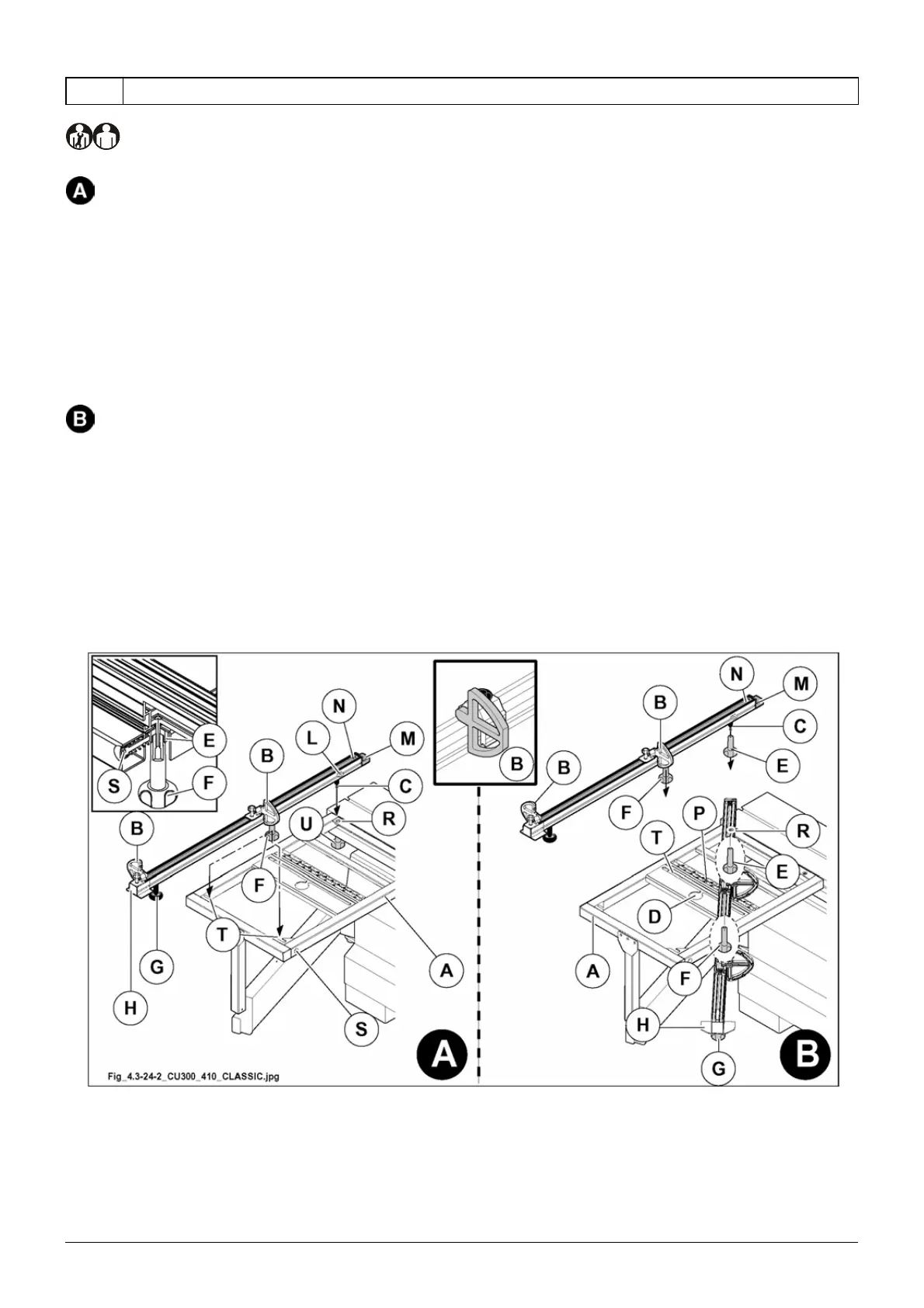
4.3.24.2 FITTING THE REST RULE
(hd_4.3.24.2_0.0)
Installation for 90° cuts
1) Place the telescopic ruler on the table (A fig. 4.3-24-2), inserting the fulcrum (C fig. 4.3-24-2) in the hole (R
fig. 4.3-24-2).
Insert the knob (F fig. 4.3-24-2) in the slot (T fig. 4.3-24-2).
2) Position the telescopic ruler in such a way that the pin (C fig. 4.3-24-2) fits into place against the gib (L fig.
4.3-24-2). The gib (L fig. 4.3-24-2) is adjusted by our technicians and is used to rapidly position the
telescopic ruler at the right distance from the saw blade (only at a 90° position).
3) Position the telescopic ruler in such a way that the pin (E fig. 4.3-24-2) fits into place against the device (S
fig. 4.3-24-2).
4) Tighten the knobs (F fig. 4.3-24-2) and (U fig. 4.3-24-2).
Installation for inclined cuts
1) Place the telescopic ruler on the table (A fig. 4.3-24-2), inserting the fulcrum (C fig. 4.3-24-2) in the hole (R
fig. 4.3-24-2).
Insert the knob (F fig. 4.3-24-2) in the slot (T fig. 4.3-24-2) by means of the hole (D fig. 4.3-24-2).
2) For use, position the ruler referring to the plate (P fig. 4.3-24-2).
3) Tighten the knobs (F fig. 4.3-24-2) and (E fig. 4.3-24-2).
The ruler is fitted with an extractable telescopic extension (H fig. 4.3-24-2), which may be lengthened as
required after loosening the knob (G fig. 4.3-24-2).
When the chip guard (M fig. 4.3-24-2) is worn, bring it up to the saw blade by loosening the two screws (N
fig. 4.3-24-2).
Fig. 4.3-24-2