7 - SUPPORTING FRAME AND FENCE FOR PARALLEL CUTS: USE AND
ADJUSTMENT
EN
Pag. 26/26 - Cap. 7 THIS MANUAL IS PROPERTY OF SCM INDUSTRIA S.P.A - ANY TOTAL OR PARTIAL REPRODUCTION IS STRICTLY FORBIDDEN
7.25 ADDITIONAL RULE FOR OBLIQUE CUTS WITH
MILLIMETER RULE
(ev_7-25_0.0)
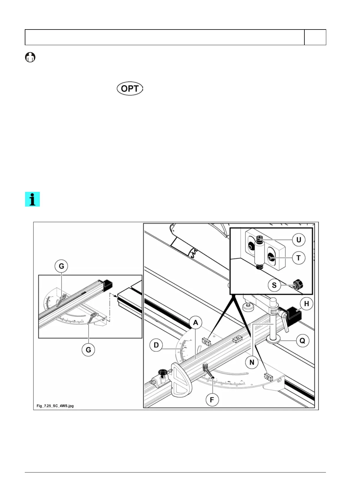
- Unlock the ruler assembly by turning (counterclockwise) the stud bolt (N fig. 7.25);
- loosen handle (F fig. 7.25);
- position the ruler assembly at the right distance from the saw blade;
- for mitre cuts turn the fence unit (A fig. 7.25) using scale (D fig. 7.25) as a reference;
- block by tightening handle (F fig. 7.25);
- position the presser up against the ruler assembly ensuring that the washer (Q fig. 7.25) is inserted into the
groove;
- lock the ruler assembly by turning (clockwise) the stud bolt (N fig. 7.25).
The table has already been adjusted; to adjust proceed as follows:
- loosen levers (G fig. 7.25);
- adjust the dowels (S fig. 7.25) to ensure the table is parallel to the wagon;
- loosen screws (T fig. 7.25) and move the dowels (U fig. 7.25) to adjust the height position.
NOTE-INFORMATION:
when the chip guard (H fig. 7.25) is worn, move it after having loosened the retaining screws.
Fig. 7.25