3 Installation
19
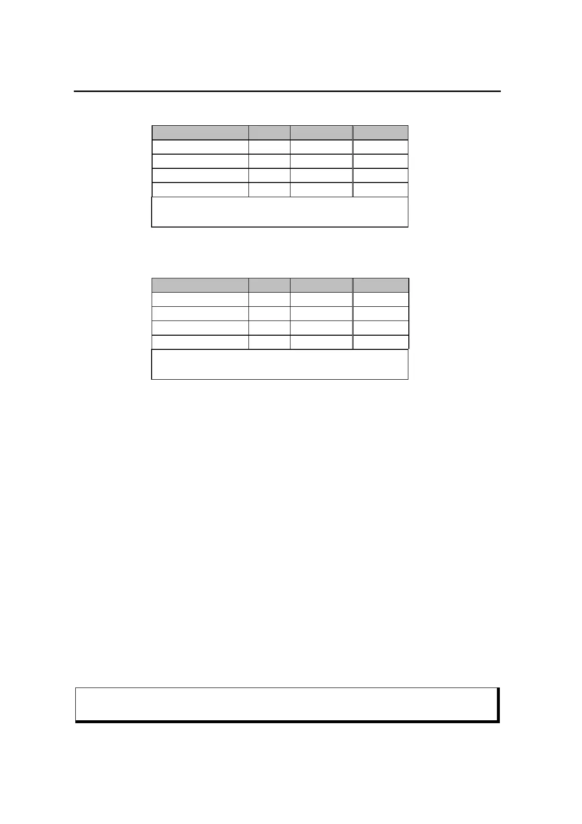
- For HF and 1k2 Packet-Radio:
Signal PTC Color YAESU
GND PIN 2 white PIN 2
PTT PIN 3 yellow PIN 3
AF-OUT PIN 1 violet PIN 1
AF-IN PIN 4 green PIN 5
This cable is available completely assembled.
Refer to chapter 16 on page 193.
Table 3.9: YAESU 6 pin Mini-DIN
- For 9k6 Packet-Radio:
Signal PTC Color YAESU
GND PIN 2 white PIN 2
PTT PIN 3 yellow PIN 3
AF-OUT PIN 1 violet PIN 1
AF-IN PIN 4 green PIN 4
This cable is available completely assembled.
Refer to chapter 16 on page 193.
Table 3.10: YAESU 6 pin Mini-DIN
3.5.4 Amplitude Adjustment
The PTC-IIIusb output amplitude has to be adjusted very carefully to the connected
transceiver. If you don’t pay attention on this item a signal much too wide will be the
result!
The output amplitude are adjusted separately depending on the modes FSK (PACTOR-1,
AMTOR, RTTY, etc). and the modes PSK (PACTOR-2). A common adjustment with one
command was in practice not the best way.
The audio input sensitivity of most transceivers is adapted to the output voltage of a
common dynamic microphone. 100 % modulation is reached at low MIC-Gain settings
with 200 mV (Peak to peak) input voltage. It is not recommended to use very high
PSKAmpl values and compensate this by lowering the MIC-Gain setting, because this
may already overdrive the first amplifier stages which are very sensitive and located in
the signal path before the MIC-Gain controlling device. We recommend for the first
approach to use the default PSKA value of 140 and then regulate the output power for
PSK with the mic-gain setting (if available). To do this connect the TRX to a dummy load
resistor capable to dissipate the power or to an antenna with good SWR (Take care that
the frequency being used is not already occupied). Entering U 3 <Return> starts the
Unproto mode 3 (=100 Bd DBPSK). Now you can use the MIC-Gain knob to increase the
transmitting power until the ALC voltage reaches the allowed limit.
Don’t overdrive the TRX because in this case the signal will be spreaded by
intermodulation!


 To Next Page