3 Installation
3.6 Transceiver Remote Control
The SCS PTC-IIIusb is equipped with a connector for controlling all the usual modern
amateur radio transceivers. Virtually all newer transceivers from KENWOOD, ICOM,
YAESU, SGC and R&S allow remote controlling of various functions, via a serial
interface. Depending on type and manufacturer, almost all the transceiver parameters can
be called up and changed. For example frequency, filter, operating mode, and much more,
can be controlled. With radio equipment that is digitally controlled, the list of functions is
almost unlimited.
The PTC-IIIusb uses this features mainly to set and readout the frequency of the
transceiver. You find more about that in chapter 13 on page 165.
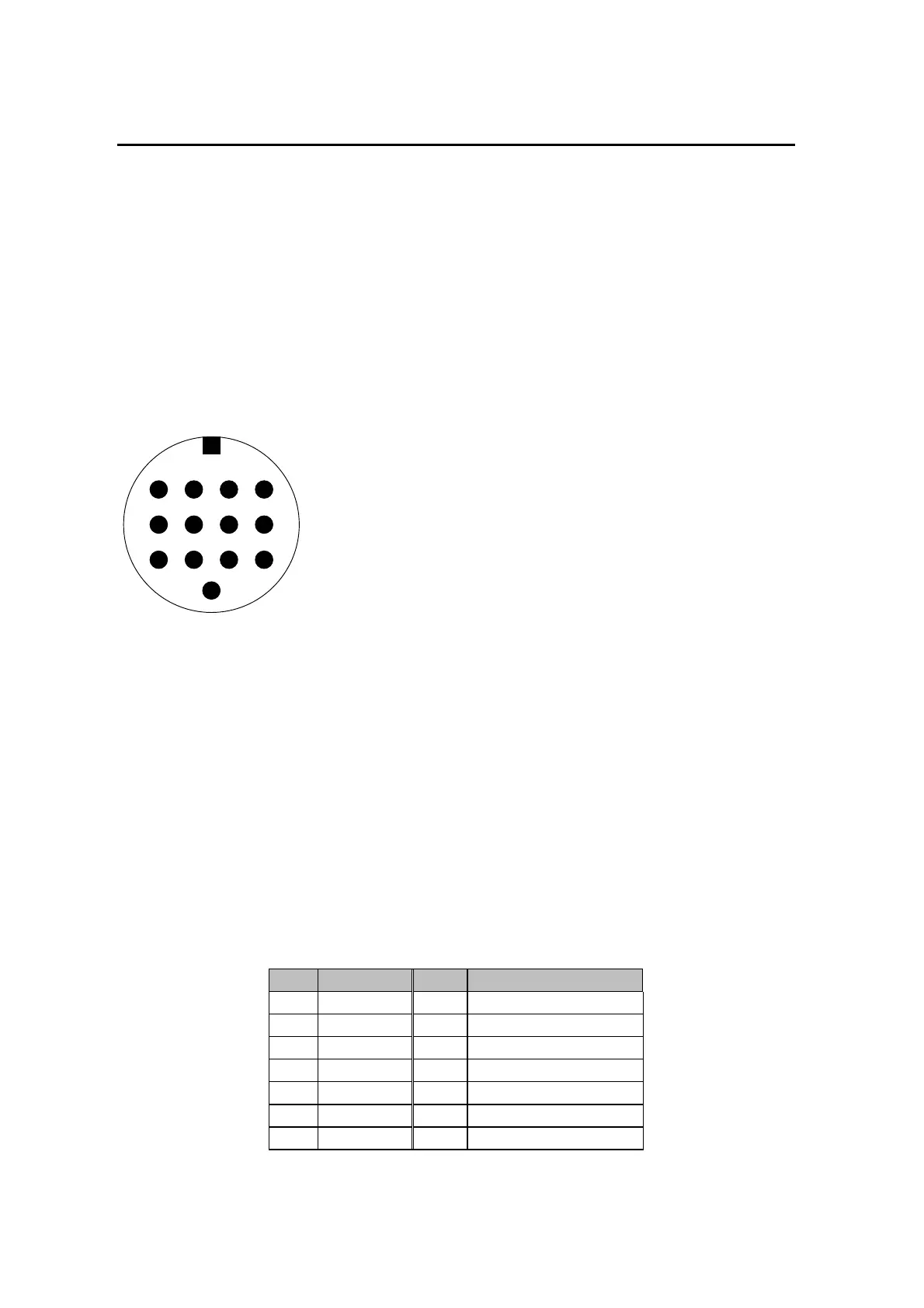
The remote-control socket is connected as follows. (seen from the back of the unit):
243
5678
9
13
1
101112
21
Figure 3.4: Transceiver remote-control
TxD TTL
Transmit data from the PTC to the transceiver. TTL-level!
RxD TTL
Receive data from the transceiver to the PTC. TTL-level!
CTS TTL
Handshake signal from the transceiver to the PTC. TTL-level!
RTS TTL
Handshake signal from the PTC to the transceiver. TTL-level!
TxD V24
Transmit data from the PTC to the transceiver. V24-level!
RxD V24
Receive data from the transceiver to the PTC. V24-level!
CTS V24
Handshake signal from the transceiver to the PTC. V24-level!
RTS V24
Handshake signal from the PTC to the transceiver. V24-level!
ICOM
Special bi-directional data signal for controlling ICOM equipment.
GND
Ground.
Pin 1: RxD TTL.
Pin 2: RTS V24.
Pin 3: TXD V24.
Pin 4: CTS V24.
Pin 5: CTS TTL.
Pin 6: ICOM.
Pin 7: Not connected.
Pin 8: RxD V24.
Pin 9: TxD TTL.
Pin 10: RTS TTL.
Pin 11: Not used.
Pin 12: Not used.
Pin 13: GND.
To connect the PTC-IIIusb to your transceiver use the attached 13-pole DIN-cable.
PIN Color PIN Color
1 violet 8 red
2 white 9 pink
3 yellow 10 light blue
4 green 11 black/white
5 blue 12 grey
6 black 13 orange
7 brown
Table 3.11: Cable Colors: 13-pole DIN-cable


 To Next Page