7
Installation Instructions and Owner's Manual
MM
+
–
PROTAP
ON/OFF
J7: JPSW_DN
J6: JPSW_UP
J12: SENDER_GND
J13: SENDER_SIG
JACKPLATE HARNESS DW0334
ACTUATOR
UP RELAY
2 WIRES
2 WIRES
ACTUATOR
DOWN RELAY
J9: SS0_POWER
J18: CAN0_GND
NMEA2000
NETWORK
J15: CAN0_H
J16: CAN0_L
J17: CAN0_POWER
J1: BATT+
J2: BATT–
J11: JP0_DN (GREEN)
J10: JP0_UP (BLUE)
J5: PROTAP_SW
J19: DIGITAL_IO2
(PINK)
(BLUE)
(YELLOW)
PROTRIM
SWITCH INPUT
JACKPLATE
SMARTSTICK GAUGE
(OPTIONAL)
JACKPLATE
ENGINE
(NOT SUPPLIED BY SEASTAR)
OEM DIGITAL
TRIM SENDER
+12V
NOTE: IF NO GAUGE, CONNECT SMARTSTICK
GROUND SS0_GND TO J8
BUZZER
(OPTIONAL)
(GREEN)
IGNITION SWITCH
+12V
NOTE: FOR TRIM SIGNAL CONNECT TO EITHER NEMA 2000
NETWORK OR TO OEM DIGITAL TRIM SENDER
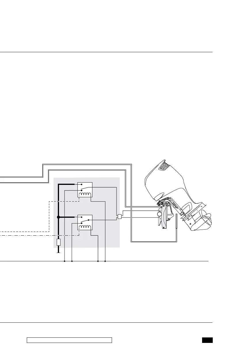
Referring to figure 4-1 on page 12 match the wiring
in the schematic to the pin on the controller.
Figure 3-1. Single Jackplate and Gauge.