Figure 3
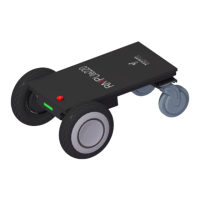
2. Take out the part shown in Figure 4, which is the part that needs
to be welded;
Figure 4
3. As shown in Figure 5, the pin angle number of the connector can
be seen from one side of the component, and then rotate it 180 °,
which is the part needs to be welded;
Figure 5
4. Use the AWG 26 cables to weld according to the pin angle
definition in the welding manual (see appendix III for details). After
the welding is completed, as shown in Figure 6;
 Loading...