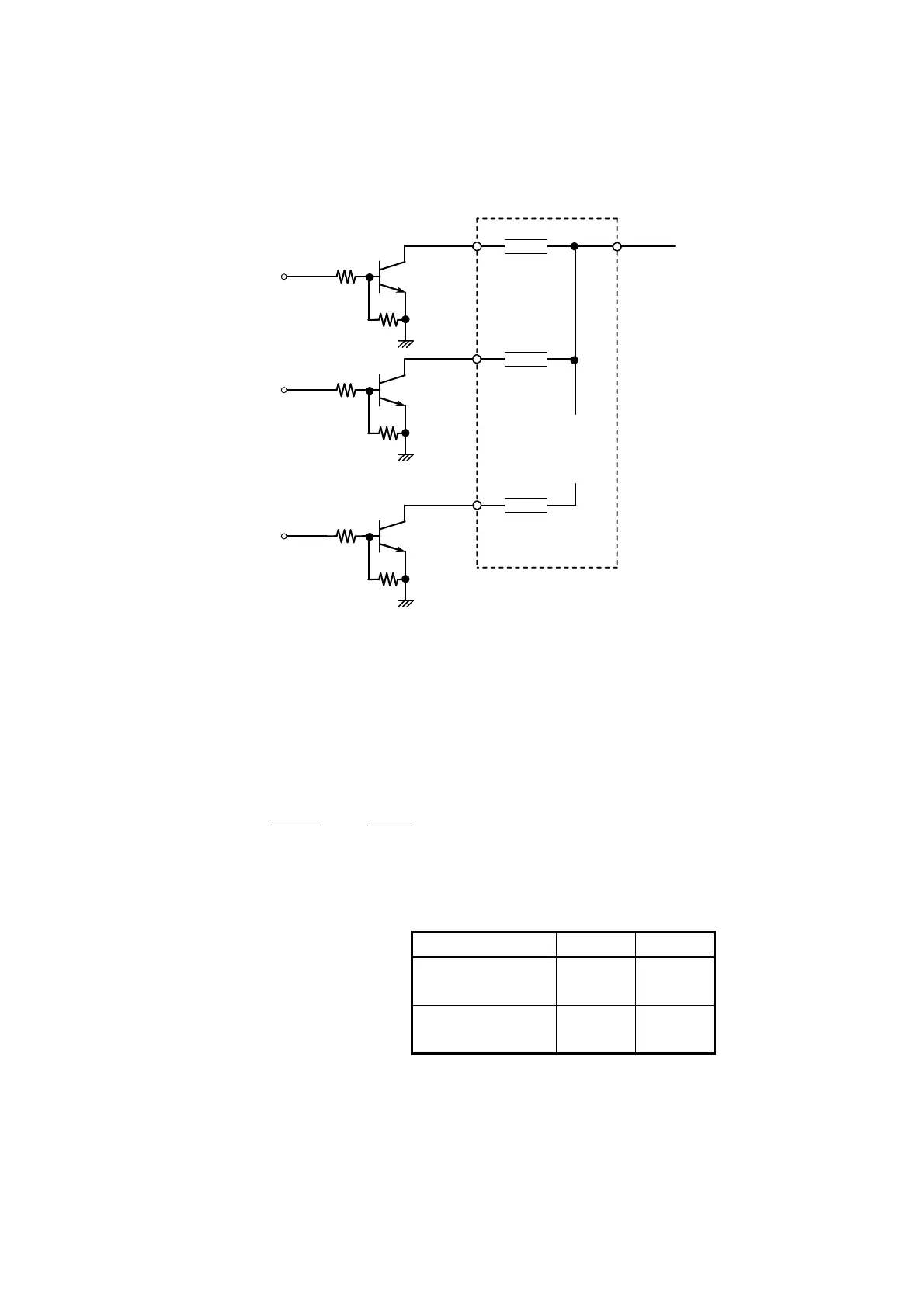
Vcc
H-COM
Dot 1
2.2kΩ
2SC5585
Head drive
signal 1
・
・
・
・
・
・
・
・
・
・
・
・
10kΩ
10kΩ
2.2kΩ
10kΩ
2.2kΩ
2SC5585
2SC5585
Dot 2
Head drive
signal 2
Head drive
signal 8
Dot 8
Figure 2-8 Sample Thermal Head Drive Circuit
2.6.2 Head Applied Energy Correction
Use the Applied Energy Correction Formula below to correct for when the power voltage and ambient
temperature fluctuation during operation (see sample pulse width control circuit).
Applied energy correction formula
)
100
TT
1(E
V2
VV
E
0
0
0 −
+
+
=
E: Applied energy (mJ)
V: FPC terminal volatage (V)
T: Temperature (°C)
E
0
: Rated energy (mJ)
B head G head
High sensitive
thermal paper
2.3mJ 2.3mJ
Standard thermal
paper
2.5mJ 2.5mJ
V
0
: Rated voltage (5.0V)
T
0
: Room temperature (24°C)
2-11

 Loading...