CHAPTER 8
DESIGN OF PERIPHERAL DEVICES
8.1 DESIGN PRECAUTIONS
The mounting procedure for MTP Series printers differs somewhat between the MTP102 and the other
printers in the series.
Mount the printer so that it is not warped or distorted in any way.
8.1.1 MTP102 Printer
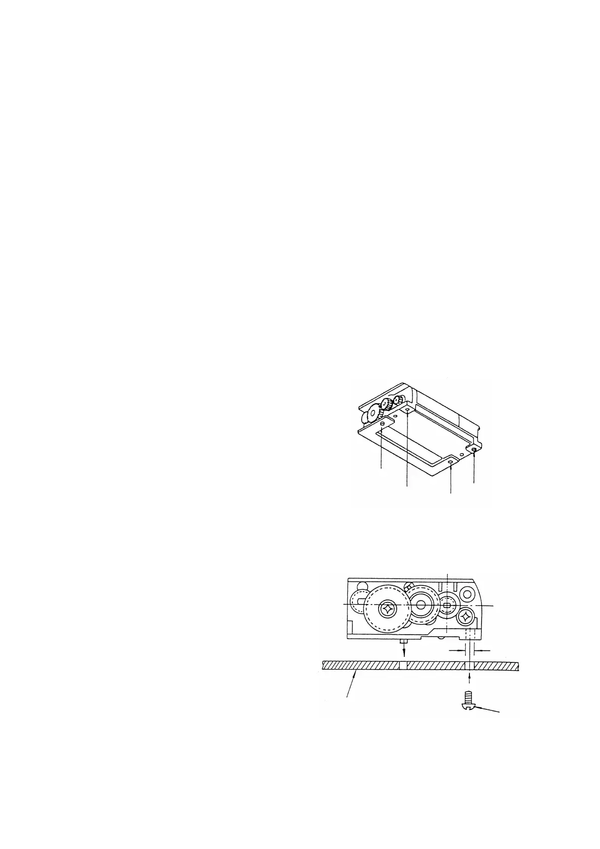
The MTP102 is provided on its back two
dowels and two holes diagonally for mounting
the printer (see Figure 8-1).
Dowel
Dowel
Hole
Hole
(1) When mounting with screws
Mount the printer by tightening the
tapping screws from under the
mounting base.
In this case, the dowels are used as a
reference for positioning (see Figure
8-2).
Figure 8-1 MTP102 Printer (Back)
φ2mm
Printer mounting base
Tapping screw
Figure 8-2 Mounting with Screws
(MTP102 Printer)
8-1
 Loading...