U.6.22
SEL-421/SEL-421-1 Relay User’s Guide Date Code 20020501
Testing and Troubleshooting
Test Methods
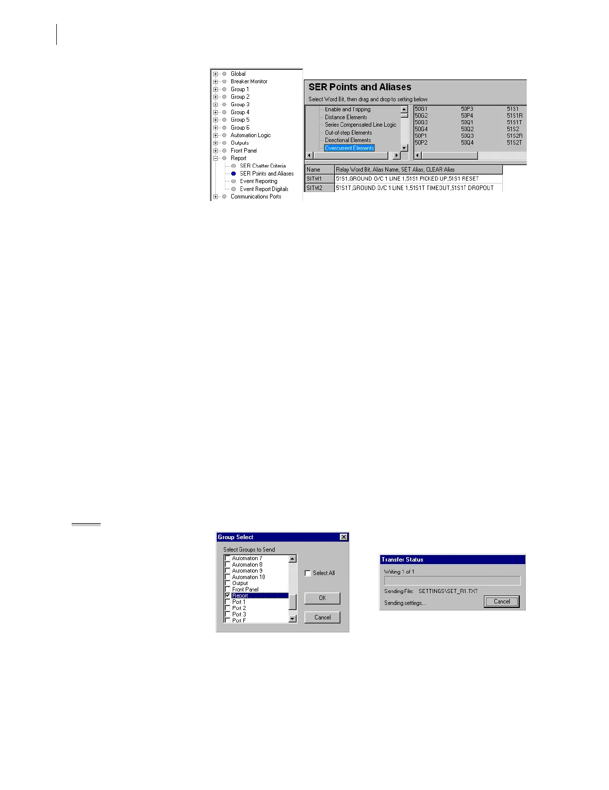
Figure 6.14 Setting SER Points and Aliases: ACSELERATOR Software.
Step 4. Enter SER element names and aliases. Type the SER points and
aliases in the open text boxes beginning at SITM1. Click
Overcurrent Elements in the Relay Word Bits column on the
left of the SER Points and Aliases dialog box to see a list of
available overcurrent elements. Select, click, and drag the 51S1
element from the right side of the SER Points and Aliases
dialog box to text box SITM1. For this example enter
51S1,GROUND O/C 1 LINE 1,51S1 PICKED UP,51S1
RESET for SITM1, and enter 51S1T,GROUND O/C 1 LINE
1,51S1T TIMEOUT,51S1T DROPOUT for SITM2 as shown
in Figure 6.14.
You can enter as many as 250 relay elements in the SER Points
and Aliases list. See SER (Sequential Events Recorder) on
page A.3.34 in the Applications Handbook.
Step 5. Save the new settings in the
ACSELERATOR software. On the
File menu, click Save.
Step 6. Upload the new settings to the SEL-421 Relay. On the File
menu, click Send. The
ACSELERATOR software prompts you
for the settings class you want to send to the relay, as shown in
the Group Select dialog box of Figure 6.15. Click the check
box for Group 1 and for Report. Click OK. The
ACSELERATOR
software responds with a Transfer Status dialog box as in
Figure 6.15. If you see no error message, the new settings are
loaded in the relay.
NOTE: The Relay Editor dialog boxes
shown in Figure 6.15 are for the
SEL-421 Relay. The SEL-421-1 Relay
dialog boxes are similar.
Figure 6.15 Uploading Group 1 and Report Settings to SEL-421 Relay.
Step 7. Connect a test source to the relay. Set the current output of a
test source to zero output level. Connect a single-phase current
output of the test source to the IAW analog input (see
Figure 6.5 on page 6.12 and Secondary Circuits on page U.2.5
in the User’s Guide).