U.2.12
SEL-421/SEL-421-1 Relay User’s Guide Date Code 20020501
Installation
Plug-In Boards
Plug-In Boards
The SEL-421 Relay is available in many input/output configuration options.
The relay base model is a 3U chassis with Standard I/O and screw terminal
connector connections (see Figure 2.3 on page 2.5). Other ordering options
include versions of the relay in larger enclosures (4U or 5U) with all, partial,
or no extra I/O boards installed.
NOTE: Ordering the 4U and 5U relay
with partial or no extra I/O allows for
future system expansion and future
use of additional relay features.
Also available for the SEL-421 Relay is a plug-in communications card. The
optional SEL-2701 Ethernet Processor communications card allows you to
use TCP/IP, FTP, Telnet, and UCA2 applications on an Ethernet network.
I/O Interface Boards
You can choose among three input/output interface boards for the I/O slots of
the 4U and 5U chassis. These I/O interface boards are in addition to the main
board I/O described in Shared Configuration Attributes on page 2.2. The I/O
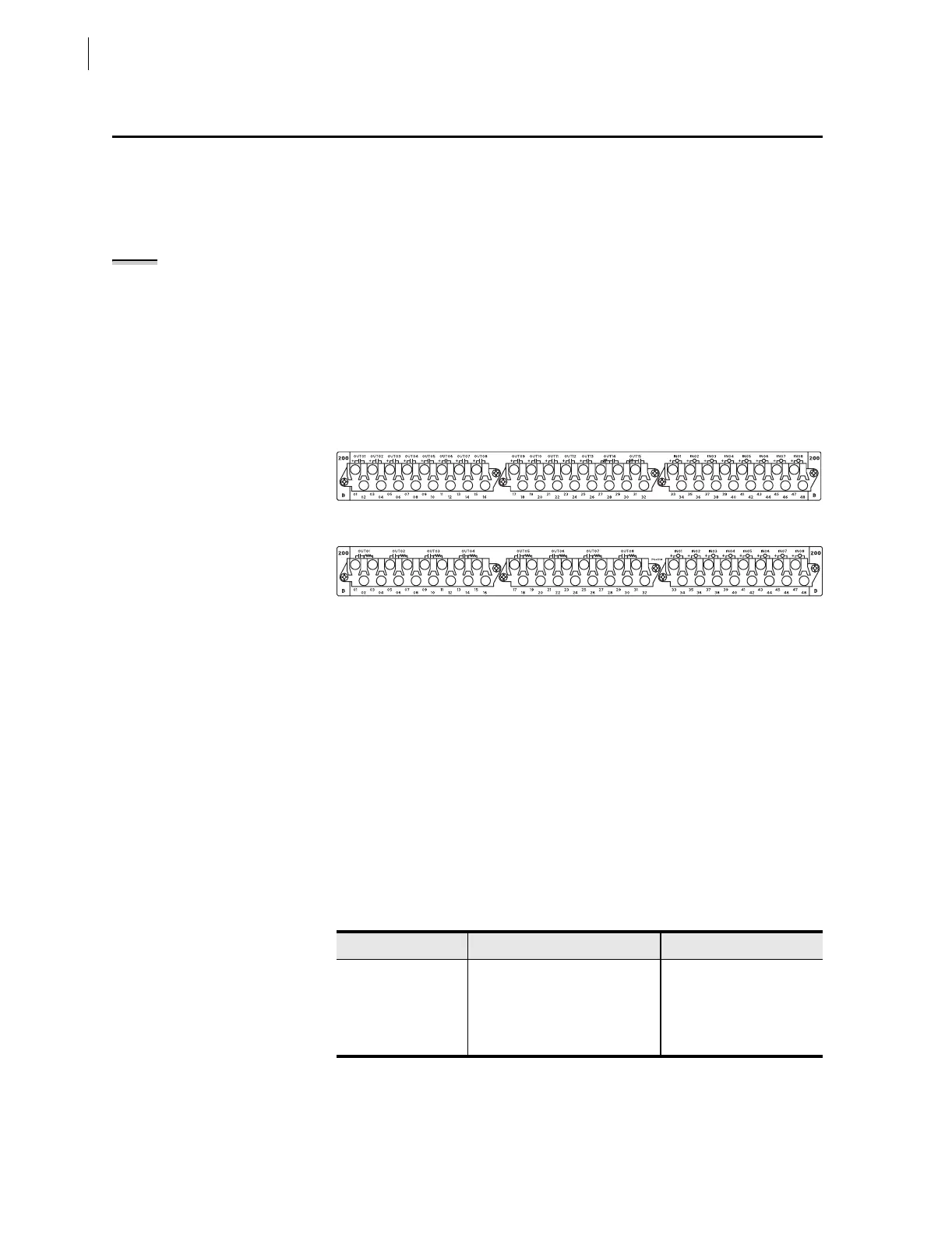
interface boards are INT1, INT5, and INT6. Figure 2.10 and Figure 2.11 show
the rear screw terminal connectors associated with these interface boards.
Figure 2.10 INT1 or INT6 I/O Interface Board.
Figure 2.11 INT5 I/O Interface Board.
The I/O interface boards carry jumpers that identify the board location. See
Jumpers on page 2.17 for more information on I/O board jumpers.
I/O Interface Board Inputs
All optional I/O interface boards have eight independent control inputs. All
independent inputs are isolated from other inputs. These high-isolation control
inputs are polarity-sensitive, ground-isolated circuits. You cannot damage
these inputs with a reverse polarity connection; though, the relay will not
detect input changes with a reverse-polarity input.
Table 2.1 is a comparison of the I/O board input capacities; the table also
shows the I/O inputs on the main board. See Control Inputs on page U.1.11 in
the User’s Guide for complete control input specifications.
.
Table 2.1 I/O Interface Boards Control Inputs
Board Number Independent Contact Pairs Common Contact Pairs
INT1 8
INT5 8
INT6 8
Main Board 5 2