Description of operation of the power sources and technical dates 11
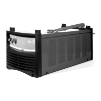
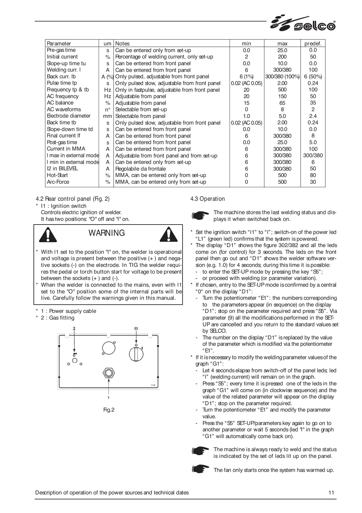
4.2 Rear control panel (Fig. 2)
* I1 : Ignition switch
Controls electric ignition of welder.
It has two positions: "O" off and "l" on.
* With l1 set to the position "l" on, the welder is operational
and voltage is present between the positive (+ ) and nega-
tive sockets (-) on the electrode. In TIG the welder requi-
res the pedal or torch button start for voltage to be present
between the sockets (+ ) and (-).
* When the welder is connected to the mains, even with l1
set to the "O" position some of the internal parts will be
live. Carefully follow the warnings given in this manual.
* 1 : Power supply cable
* 2 : Gas fitting
Fig.2
4.3 Operation
The machine stores the last welding status and dis-
plays it when switched back on.
* Set the ignition switch “l1” to “l”; switch-on of the power led
“L1” (green led) confirms that the system is powered.
* The display “D1” shows the figure 302/382 and all the leds
come on (for control) for 3 seconds. The leds on the front
panel then go out and “D1” shows the welder software ver-
sion (e.g. 1.0) for 4 seconds; during this time it is possible:
- to enter the SET-UP mode by pressing the key “S5”;
- or proceed with welding (or parameter variation).
* If chosen, entry to the SET-UP mode is confirmed by a central
“0“ on the display “ D1”:
- Turn the potentiometer “ E1”: the numbers corresponding
to the parameters appear (in sequence) on the display
“D1”; stop on the parameter required and press “S5”. Via
parameter (9) all the modifications performed in the SET-
UP are cancelled and you return to the standard values set
by SELCO.
- The number on the display “D1” is replaced by the value
of the parameter which is modified via the potentiometer
“E1”.
* If it is necessary to modify the welding parameter values of the
graph “ G1”:
- Let 4 seconds elapse from switch-off of the panel leds; led
“l” (welding current) will remain on in the graph.
- Press “S5”; every time it is pressed one of the leds in the
graph “ G1” will come on (in clockwise sequence) and the
value of the related parameter will appear on the display
“D1”; stop on the parameter required.
- Turn the potentiometer “E1” and modify the parameter
value.
- Press the “ S5” SET-UP/parameters key again to go on to
another parameter or wait 5 seconds (led "l" in the graph
“G1” will automatically come back on).
The machine is always ready to weld and the status
is indicated by the set of leds lit up on the panel.
The fan only starts once the system has warmed up.
WARNING
Parameter
Pre-gas time
Initial current
Slope-up time tu
Welding curr. l
Back curr. lb
Pulse time tp
Frequency tp & tb
AC frequency
AC balance
AC waveforms
Electrode diameter
Back time tb
Slope-down time td
Final current lf
Post-gas time
Current in MMA
l max in external mode
l min in external mode
l2 in BILEVEL
Hot-Start
Arc-Force
um
s
%
s
A
A (%)
s
Hz
Hz
%
n°
mm
s
s
A
s
A
A
A
A
%
%
min
0.0
2
0.0
6
6 (1%)
0.02 (AC 0.05)
20
20
15
0
1.0
0.02 (AC 0.05)
0.0
6
0.0
6
6
6
6
0
0
max
25.0
200
10.0
300/380
300/380 (100%)
2.00
500
150
65
8
5.0
2.00
10.0
300/380
25.0
300/380
300/380
300/380
300/380
500
500
predef.
0.0
50
0.0
100
6 (50%)
0.24
100
50
35
2
2.4
0.24
0.0
8
5.0
100
300/380
6
50
80
30
Notes
Can be entered only from set-up
Percentage of welding current, only set-up
Can be entered from front panel
Can be entered from front panel
Only pulsed, adjustable from front panel
Only pulsed slow, adjustable from front panel
Only in fastpulse, adjustable from front panel
Adjustable from panel
Adjustable from panel
Selectable from set-up
Selectable from panel
Only pulsed slow, adjustable from front panel
Can be entered from front panel
Can be entered from front panel
Can be entered from front panel
Can be entered from front panel
Adjustable from front panel and from set-up
Can be entered only from set-up
Regolabile da frontale
MMA, can be entered only from set-up
MMA, can be entered only from set-up