Description of operation of the power sources and technical dates 9
The contents of this chapter are of vital importance and the-
refore necessary for operation of the warranties. The manu-
facturer accepts no liability if the operator fails to observe
the above precautions and instructions.
4.0 MACHINE DESCRIPTION
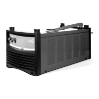
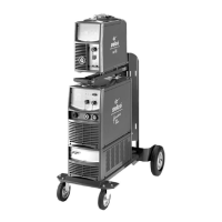
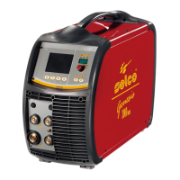
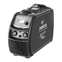
The Genesis 302 AC/DC e Genesis 382 AC/DC power sources
offer excellent performance in the following welding procedures:
- TIG AC with square, sine and triangular wave;
- TIG DC with remote arc striking with high frequency (TIG HF-
START) and gas delivery control via torch button;
- TIG DC with contact start with reduction of short circuit current
(TIG LIFT-START) and gas delivery control via torch button;
- MMA.
In inverter welders the output current is insensitive to variations
in the power supply voltage and length of the arc and is per-
fectly levelled, providing best weld quality.
On all the power sources features the following devices:
- a positive socket (+ ), a negative socket (-) and a central soc-
ket for connection of the TIG torch
- a front control panel with socket for remote controls
- RC16 potentiometer remote control for MMA and TIG
welding (optional)
- RC12 pedal remote control for TIG welding (optional)
- a rear control panel with gas socket
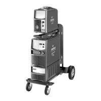
The Genesis 302 AC/DC and Genesis 382 AC/DC can be sup-
plied with WU21 cooling unit for liquid cooling of the TIG
torch.
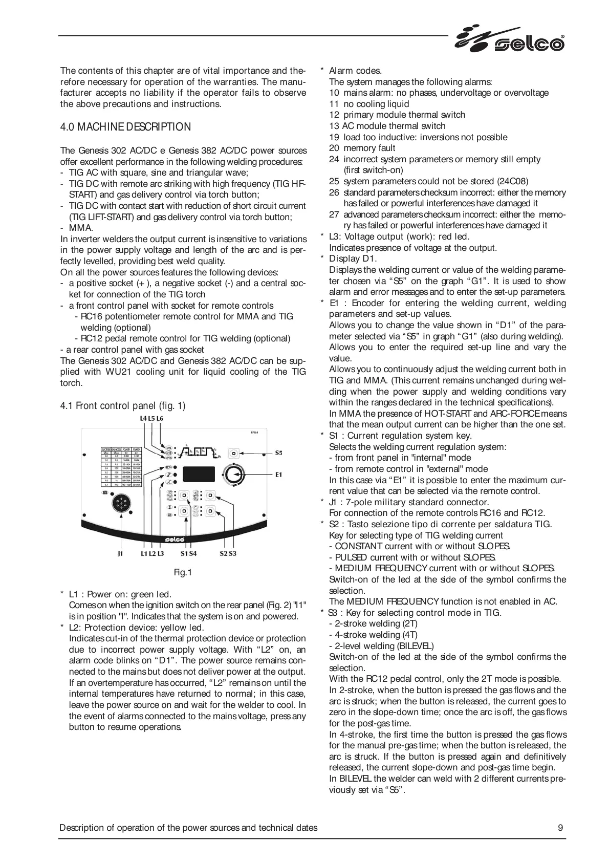
4.1 Front control panel (fig. 1)
Fig.1
* L1 : Power on: green led.
Comes on when the ignition switch on the rear panel (Fig. 2) "I1"
is in position "I". Indicates that the system is on and powered.
* L2: Protection device: yellow led.
Indicates cut-in of the thermal protection device or protection
due to incorrect power supply voltage. With “L2” on, an
alarm code blinks on “D1”. The power source remains con-
nected to the mains but does not deliver power at the output.
If an overtemperature has occurred, “L2” remains on until the
internal temperatures have returned to normal; in this case,
leave the power source on and wait for the welder to cool. In
the event of alarms connected to the mains voltage, press any
button to resume operations.
* Alarm codes.
The system manages the following alarms:
10 mains alarm: no phases, undervoltage or overvoltage
11 no cooling liquid
12 primary module thermal switch
13 AC module thermal switch
19 load too inductive: inversions not possible
20 memory fault
24 incorrect system parameters or memory still empty
(first switch-on)
25 system parameters could not be stored (24C08)
26 standard parameters checksum incorrect: either the memory
has failed or powerful interferences have damaged it
27 advanced parameters checksum incorrect: either the memo-
ry has failed or powerful interferences have damaged it
* L3: Voltage output (work): red led.
Indicates presence of voltage at the output.
* Display D1.
Displays the welding current or value of the welding parame-
ter chosen via “ S5” on the graph “G1”. It is used to show
alarm and error messages and to enter the set-up parameters.
* E1 : Encoder for entering the welding current, welding
parameters and set-up values.
Allows you to change the value shown in “D1” of the para-
meter selected via “ S5” in graph “ G1” (also during welding).
Allows you to enter the required set-up line and vary the
value.
Allows you to continuously adjust the welding current both in
TIG and MMA. (This current remains unchanged during wel-
ding when the power supply and welding conditions vary
within the ranges declared in the technical specifications).
In MMA the presence of HOT-START and ARC-FORCE means
that the mean output current can be higher than the one set.
* S1 : Current regulation system key.
Selects the welding current regulation system:
- from front panel in "internal" mode
- from remote control in "external" mode
In this case via “ E1” it is possible to enter the maximum cur-
rent value that can be selected via the remote control.
* J1 : 7-pole military standard connector.
For connection of the remote controls RC16 and RC12.
* S2 : Tasto selezione tipo di corrente per saldatura TIG.
Key for selecting type of TIG welding current
- CONSTANT current with or without SLOPES.
- PULSED current with or without SLOPES.
- MEDIUM FREQUENCY current with or without SLOPES.
Switch-on of the led at the side of the symbol confirms the
selection.
The MEDIUM FREQUENCY function is not enabled in AC.
* S3 : Key for selecting control mode in TIG.
- 2-stroke welding (2T)
- 4-stroke welding (4T)
- 2-level welding (BILEVEL)
Switch-on of the led at the side of the symbol confirms the
selection.
With the RC12 pedal control, only the 2T mode is possible.
In 2-stroke, when the button is pressed the gas flows and the
arc is struck; when the button is released, the current goes to
zero in the slope-down time; once the arc is off, the gas flows
for the post-gas time.
In 4-stroke, the first time the button is pressed the gas flows
for the manual pre-gas time; when the button is released, the
arc is struck. If the button is pressed again and definitively
released, the current slope-down and post-gas time begin.
In BILEVEL the welder can weld with 2 different currents pre-
viously set via “S5”.
 Loading...