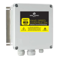
User Manual ESY-1 / rev. 9 15.01.2008 www.selproweb.com
19
8
9
10
11
12
131
2
3
4
5
6
7
+1
+2
+3
+4
+5
+6
SP
adj.
-6
-5
-4
-3
-2
-1
SP
adj.
Gnd
SP2
+10V
OUT
5
8
9
7
6
10
4
3
2
1
9
10
5
8
7
6
4
3
2
1
CUT-OFF
(MIN OUT)
MAX OUT
SP2
SP1
8
9
10
131
2
3
4
5
6
1
SP1
SP1
+1
+2
+3
+6- 6
-5
-4
-3
-2
-1
SP1 adj .
7
8
9
10
131
2
3
4
5
6
2
SP2
SP2
+1
+2
+3
+6- 6
-5
-4
-3
-2
-1
SP2 adj .
7
+4
+5
+4
+5
11
12
11
12
8
9
10
11
12
131
2
3
4
5
6
+1
+2
+3
+4
+5
+6
-6
-5
-4
-3
-2
-1
SP2 adj.
+/-
Gnd
SP2
+10V
OUT
8
9
10
11
12
131
2
3
4
5
6
+1
+2
+3
+4
+5
+6
-6
-5
-4
-3
-2
-1
SP1 adj.
+/-
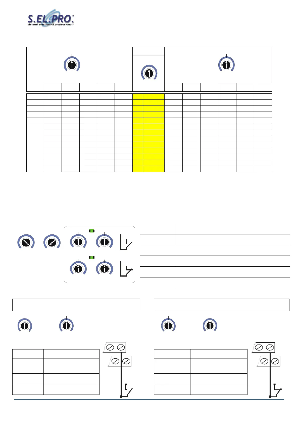
9.5.7. Set-Point values, range 10°C to 60°C (NTC probe 10kohm@25°C)
10-60 °C
-6 -5 -4 -3 -2 -1 +1 +2 +3 +4 +5 +6
2,00 2,50 3,00 3,50 4,00 4,50
1
5 5,50 6,00 6,50 7,00 7,50 8,00
7,00
7,50 8,00 8,50 9,00 9,50
2 10 10,50 11,00 11,50 12,00 12,50
13,00
12,00
12,50 13,00 13,50 14,00 14,50
3 15 15,50 16,00 16,50 17,00 17,50
18,00
17,00
17,50 18,00 18,50 19,00 19,50
4 20 20,50 21,00 21,50 22,00 22,50
23,00
22,00
22,50 23,00 23,50 24,00 24,50
5 25 25,50 26,00 26,50 27,00 27,50
28,00
27,00
27,50 28,00 28,50 29,00 29,50
6 30 30,50 31,00 31,50 32,00 32,50
33,00
32,00
32,50 33,00 33,50 34,00 34,50
7 35 35,50 36,00 36,50 37,00 37,50
38,00
37,00
37,50 38,00 38,50 39,00 39,50
8 40 40,50 41,00 41,50 42,00 42,50
43,00
42,00
42,50 43,00 43,50 44,00 44,50
9 45 45,50 46,00 46,50 47,00 47,50
48,00
47,00
47,50 48,00 48,50 49,00 49,50
10 50 50,50 51,00 51,50 52,00 52,50
53,00
52,00
52,50 53,00 53,50 54,00 54,50
11 55 55,50 56,00 56,50 57,00 57,50
58,00
57,00
57,50 58,00 58,50 59,00 59,50
12 60 60,50 61,00 61,50 62,00 62,50
63,00
62,00 62,50 63,00 63,50 64,00 64,50
13
65 65,50 66,00 66,50 67,00 67,50 68,00
9.6. Regulation with Double SET-Point (optional)
The controller ESY-1 has been designed to be connected to an optional card with the Double Set-Point function, which allows to
determine two operating points: SP1 & SP2. The inclusion of the optional card is factory preset and must be requested when placing
the order.
In order to select the CUT-OFF / MIN out and MAX out values, follow the indications given in the table above.
For the selection of Set-Point 1 & 2 use the input SP2 + GND on the terminal block, as indicated below.
MAX OUT
Maximum RPM/VAC limit
MIN OUT
Minimum RPM/VAC or Cut-Off limit
SP1
Main Set-Point 1
(see following tables for position / value correspondence)
SP1 adj.
Set-Point 1 accurate adjustment
(see following tables for position / value correspondence)
SP2
Set-Point 2
(see following tables for position / value correspondence)
SP2 adj.
Set-Point 2 accurate adjustment
(see following tables for position / value correspondence)
In order to pass from Set-Point 1 to Set-Point 2, it is necessary to close the preset contact between terminals.
SET-POINT 1 operation SET-POINT 2 operation
SP1
Set-Point 1
SP2
Set-Point 2
SP1 adj.
Set-Point 1
adjustment
SP2 adj.
Set-Point 2
adjustment
Led 1
Led SP1 = ON
Led 2
Led SP2 = ON
SP2
OPEN
SP2
CLOSED


 To Next Page