User Manual ESY-1 / rev. 9 15.01.2008 www.selproweb.com
4
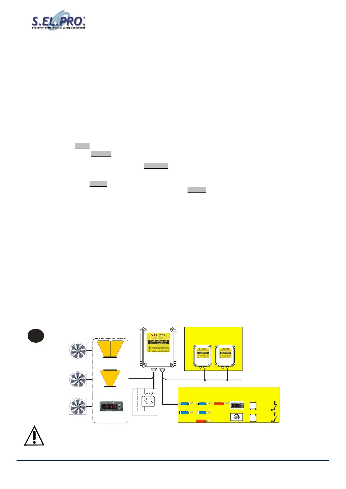
Moduli SLAVE - SLAVE units
0 - 10 Vdc
PWM
MAX n.5
ALIMENTAZIONE
PE L1 N
NTC
0- 5Vdc 0-5Vdc
0-10Vdc
SEGNALI DI REGOLAZIONE / CONTROL SIGNALS
IN1
4-20mA
IN2 IN3
4-20mA NTC
SP1
SP2
P W M
OUT SP2
0-10Vdc
IN4
0-10Vdc
for C ONDENSERs
2 Input CIRCUITs
OM mode
for DRY-Cooler
1 Input CIRCUIT
°C (NTC)
f or Rem ore Controller
1 Input CIRCUIT
BAR (mA-Vdc)
0-10Vdc
(default)
FANs
3. OPERATING MODES AND APPLICATIONS
The ESY1 devices are electronic analog regulators of single-phase AC voltage, which use the phase-cutting principle (Triac) in order
to vary the output active voltage applied to a resistive or inductive load.
When connected to asynchronous high-slip electric motors of fans or pumps, they control their rotational speed in order to maintain the
key parameter within desired values. On this purpose they have been projected and specialized for control applications on Air Cooled
Heat Exchangers, used in Air Conditioning, Refrigerating, Air Handling and Ventilation Systems.
The series is available in the following versions:
- ALL-in-ONE (multi-input), with 4 control inputs, 3 inputs for mA-Vdc-NTC sensors and 1 0-10Vdc control signal, for MASTER-
SLAVE operating modes.
- SLAVE-ONE, with 1 input for 0-10Vdc (Slave-SV) or PWM (Slave-SP) control signals, to be used as single regulation units or as
additional modules in order to share out the overall controlled power, only for SLAVE operating mode.
With the ALL-in-ONE mode, the selection of input signal and operating mode are performed automatically: the controller operates
through the presently active sensor/signal and there is NO need to use any selection or programming hardware device.
The regulator selects the currently ACTIVE control signal, according to the mode preset by the Jumpers.
It is possible to modify the factory settings during the installation procedure of the device, by moving the following JUMPERS:
J1, operating mode: DIRECT - the VAC output increases as the control signal value increases
REVERSE - the VAC output decreases as the control signal value increases
J2, VAC fans at Set Point: VAC/RMP = 100% with SP = MAX, the Set-P corresponds to the fans Max-speed
VAC/RPM = 0% with SP = MIN, the Set-P corresponds to the fans Min-speed
J3, operation of trimmer P2: MIN for the Min. AC voltage limit supplied to the connected motor;
(J1 for SLAVE-SV) Cut-Off for the AC voltage limit of the connected motor;
J4, output for Slave units control: with control signal for SLAVE-SV units, with 0-10Vdc input signal
with control signal for SLAVE-SP units, with PWM input signal
While the Proportional Band (Pb) values are already factory preset (see Table: Operating Parameters), the Set Point values are
determined through a couple of 13-position rotary switches: SP and SP
adj
., which are intended to be used quickly and easily even by
base users. The selection of the Set Point is immediate, and two LEDs (+ & -) will show the relationship between this desired value
and the signal value perceived through the presen
tly active sensor; the Set Point will be reached when both LEDs will be off.
In addition, there are LEDs indicating the selection of the First or Second Set Point (only for optional card with double Set Point), and
a LED showing the presence of power supply.
With the SLAVE-ONE version, two types of SLAVE units are available: SV (input 0-10Vdc), and SP (input PWM).
All ESY-1 units are equipped with:
– Complete galvanic separation between AC mains supply and control inputs;
– EMC mains filter with Residential, Commercial & Light Industrial limit (conformity with PDS systems), fit to
be used with equipment directly connected to the low voltage mains supply;
– Overvoltage protection on the mains supply;
– Short circuit protection on the connection of the control sensors/signals;
– Protection filters on control inputs
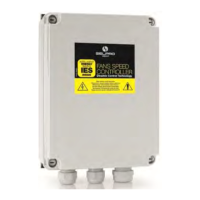
The ESY-1 series is available in the sizes 8A–12A–16A–20A, with single phase supply voltage 230V/50Hz, and it is housed in a
GW–Plast 120°C case with protection degree IP55 and high impact resistance, for out of doors installations (-20T50).
The controller can be used both in Condenser mode (pressure transducer) and in Dry-Cooler mode (temperature probe) without the
need of any further configuration or programming, with two operating SET-Points (selection of Set-Point 1 & 2), beside the Remote-
SLAVE Unit mode, when driven by an external controller generating a 0-10Vdc control signal.
60Hz applications: only with factory calibration
The regulator works correctly also with 60 Hz, but it is necessary to calibrate the output signal to 100% in order to optimize
the regulation and avoid pulse and beat frequencies.
.
i