User Manual ESY-1 / rev. 9 15.01.2008 www.selproweb.com
8
1
2
=
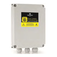
6. SIGNAL CONNECTIONS for the 4 CONFIGURATIONS (ALL-in-ONE)
After checking carefully all power supply connections, connect the input signal/s and supply the card.
The output voltage varies from zero Vac to 230 Vac, according to the variation of the control signal.
For the connection of the control signal, use an ordinary twisted-pair cable in disturbance-free environments, while in presence
of environmental electromagnetic disturbances use a shielded twisted cable with the screen connected to earth, keeping it as far
away as possible from other power cables.
The function modes, both always available in the present series, can be:
- MASTER with Set-Point, using the inputs In1–In2–In3 (for 4-20mA, 0-5Vdc or NTC probe)
- SLAVE, using the input In4 ( for 0-10V control signal)
The controllers of the ESY-1/ALL-in-ONE series can be set in the following four (4) configurations, described below.
The OM configuration is standard SELPRO
6.1. OM CONFIGURATION (STANDARD SELPRO)
N°
Na
Function
OM CONF.
1 V1
Output voltage
supply
22V (+10/-20%)
max. 25 mA
2 IN1
Transducer Input
N° 1
4-20 mA
3 GND
Ground GND
4 IN2
Transducer Input
N° 2
4-20 mA
5 V2
Output voltage
supply
22V (+10/-20%)
max. 25 mA
6 IN3
Transducer Input
N° 3
NTC 10kohm
@ 25°C
7 GND
Ground GND
8 IN4
Input N° 4 (only
SLAVE control)
0-10Vdc
9 +10V
Output voltage
supply
10,0V ±1%
10
OUT
“Slave” modules
control Output
0-10Vdc / PWM
11
GND
Ground GND
12
SP2
Set-Point 1& 2
selection Contact
Open = SP1
Closed = SP2
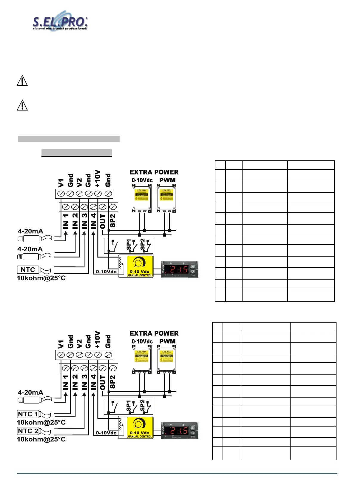
6.2. OX Configuration (on request)
N°
Name
Function
OX CONF.
1 V1
Output voltage supply
22V (+10/-20%)
max. 25 mA
2 IN1
Transducer Input
N° 1
4-20 mA
3 GND
Ground GND
4 IN2
Transducer Input
N° 2
NTC 10kohm
@ 25°C
5 V2
Output voltage supply
22V (+10/-20%)
max. 25 mA
6 IN3
Transducer Input
N° 3
NTC 10kohm
@ 25°C
7 GND
Ground GND
8 IN4
Input N° 4 (only
SLAVE control)
0-10Vdc
9 +10V
Output voltage supply +10,0V ±1%
10
OUT
“Slave” modules
control Output
0-10Vdc / PWM
11
GND
Ground GND
12
SP2
Set-Point 1& 2
selection Contact
Open = SP1
Closed = SP2