SMD 989– User Manual
Page 95 (105)
Appendix
Specifications
SMD 989 Base Unit Includes: Display, keypad, embedded controller,
Chassis/case, Power Supply/line cord
System –
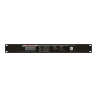
Display Type: Organic LED
Display Configuration: 256 pixels by 64 pixels
Keypad: Snap-dome Membrane
Front Panel Lockout: Password control, up to 10 alpha-numeric
characters (no punctuations or spaces allowed)
Configurations Allowed: Single Bay
Dual Bays
Rear panel: 2 independent bays
Remote Operation/Update Interface –
Type: Ethernet, 10/100
Rear panel indicators: Link (Green LED), Activity (Amber LED)
Connector: RJ45
Front Panel Indicators –
Input LED: Green indicates valid input on selected input,
Off indicates no valid signal on the selected input
Error LED: Red indicates error is occurring
OFF indicates no errors detected
10 MHz Reference Input –
Connector: (1) BNC, female
Impedance: 50 ohms
Min Level: -3 dBm
Max Level: 7 dBm
Detection: Autosensing
Return Loss: >15 dB
Monitor and Control Interfaces –
Web server GUI HTTP via web browser for Control & Monitoring
Front Panel Yes Control & Monitoring
SNMP Yes Control & Monitoring
Contact Closure Interface –
Type: (2) Electrical contact closure alarm contacts
Connector: Connector 9-pin sub-D Female
Alarms supported: User configurable to any alarm in system
Specifications are subject to change without notice.