SENNHEISER ELECTRONIC GMBH & CO. KG
COMPONENT MAINTENANCE MANUAL
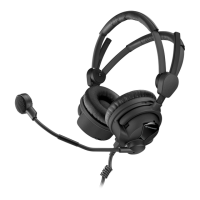
HMEC 26-SERIES
Page 7006
May 25/11
23-41-48
E. Installation of the microphone arm
NOTE:
THIS PROCEDURE IS ONLY APPLICABLE TO THE MICROPHONE SIDE CAP.
NOTE:
FOR HMEC 26, REFER TO IPL FIG. 1 AND IPL FIG. 2.
FOR HMEC 26-T, REFER TO IPL FIG. 3 AND IPL FIG. 4.
NOTE:
REPLACEMENT OF THE MICROPHONE ARM / REPLACEMENT OF THE CAP WITH MICROPHONE ARM
SUPPORT THE MICROPHONE ARM AND THE CAP WITH MICROPHONE ARM SUPPORT HAS BEEN
REDESIGNED: ALWAYS REPLACE THE CORRECT MICROPHONE ARM (REFER TO IPL).
- FOR THE HEADSETS UP TO SERIAL NO. 00200100, REFER TO FIG. 7001.
- FOR THE HEADSETS FROM SERIAL NO 00200100, REFER TO FIG. 7002.
NOTE:
BEFORE MICROPHONE ARM ASSEMBLING CHECK THAT THE PCB IS CORRECTLY INSERTED.
Procedure for headsets up to serial no. 00200100.
NOTE:
ALWAYS INSTALL THE CORRECT MICROPHONE ARM (80) WITH THE SHOWN MICROPHONE ARM
FIXING OF THE CAP (070).
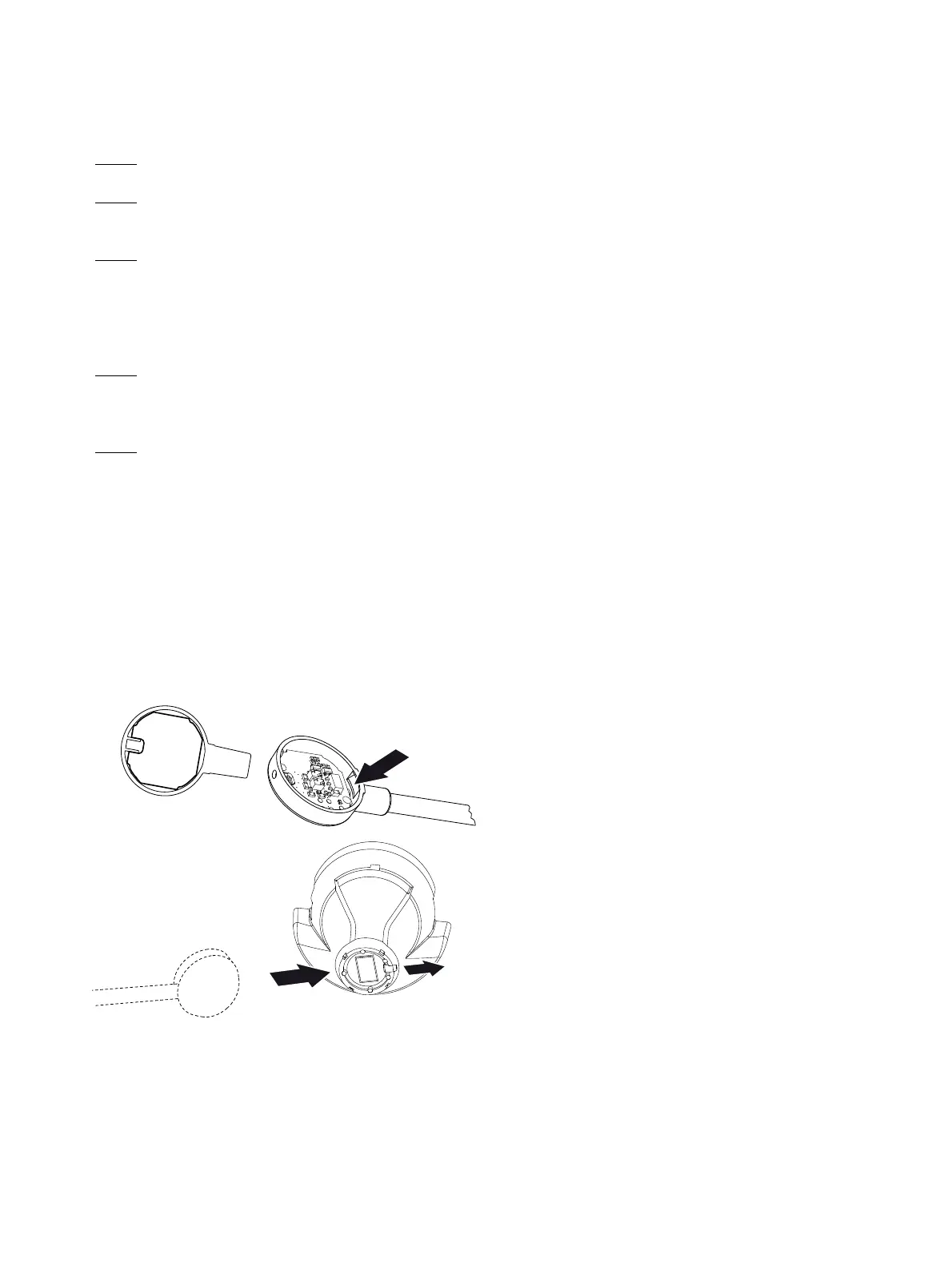
(1) There is a latch on the inner side of the microphone arm fixing .
First put this latch in the correct position on the cap (070) .
(2) Hook the microphone arm (080) into the cap (070) from the bottom.
(3) Attach the microphone arm (080) and make sure that the hole in the microphone arm fitting is
aligned with the threaded pin (020).
(4) Use a screwdriver (0.9 mm internal hexagon) to turn the threaded pin (020) out
with 0.1 to 0.3 mm above the surface of the microphone arm fixing.
Figure 7001
Installation of the microphone arm
Up to headsets serial no. 00200100
Oct 30/08
 Loading...